@Fox.FAE
Okay there are a lot of information in your reply.
I will reply in two sections:
Section I:
My design is not simply follow the DCDC Design tool. Once I see the output is abnormal I tuned the bottom resistor of the feedback resistor and make the current larger and hences the ramp can be more stable and noise immune.
So I had tried the range of 3k to 5k rather than the MPS proposed 5k or above. This is very logical that when experiment no matter what 5k to 40k the load current will always unstable and output drop to 0 and lock out.
On top of that assumption, that is why the behavior is reversed.
Q
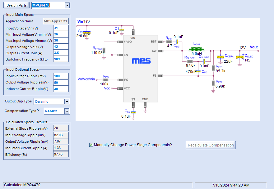
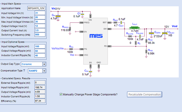
Based on the parameter given by customer as shown in Fig,1, that using RAMP2, the test result shows that it could not output required 12V, only 6.5V, which is accordance with the theory and our test result,
A
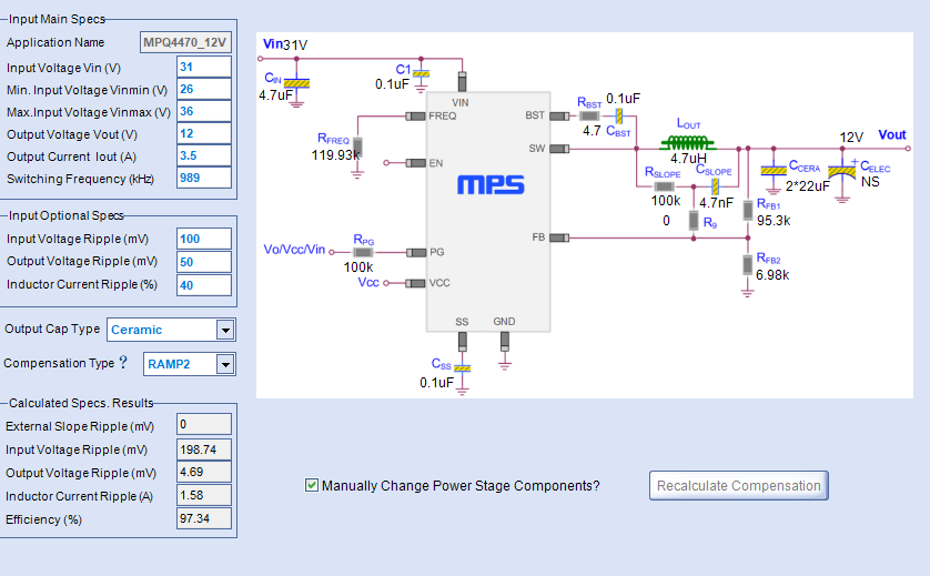
I just follow what DCDC Designer suggested from beginning of designing the 12V.
Open DCDC Designer enter 12V 5A and ~900khz to use 4.7uH in the allowed parts list.
The suggested value:
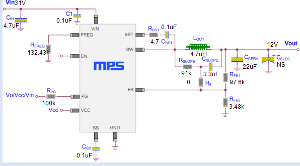
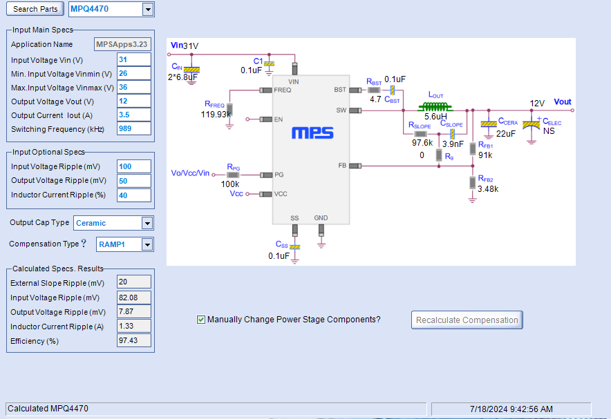
And redo by selecting RAMP2:
What result you get from DCDC Designer is what I had tried in the passed weeks.
Meantime, the DCDC Designer had updated before my post are started.
So result might have change a bit but I cannot see the proposed RAMP is valid and can achieve good result.
Section II:
I will make things more simple by just follow the document MPS that had posed and done.
“5A, 36V Synchronous Buck Converter
in a 3x4mm Package
Application Note
Prepared by Jens Hedrich
Jan. 19, 2015”
Link:https://www.monolithicpower.com/en/documentview/productdocument/index/version/2/document_type/Application%20Note/lang/en/sku/MP4470GL-Z/document_id/606/
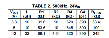
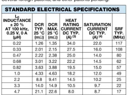
You can see MPS had done a 12V design before and using 22uH I had tried to repeat this design by due to inductor parts on hands are limited to only 10uH and 15uH. I am not sure this is RAMP1 or RAMP2 design but I still cannot see this can be regulate normally when using RAMP2 nor RAMP1 configuration.
Based on this configuration the voltage will drop at the end of the PSM and jump up at the beginning of CCM and completed die after some point of the load current.
I cannot see why the measurement data can be achieved and repeated.
So please check if this data is repeatable on 10uH as 12V 500kHz do not require 22uH from theory.
Additional Comments:
Well MPS I do see all units are helping out by after 9 years of this product why there are no solution to settle 12V and 24V.
And so it is also proposing that the DCDC Design Tools are having trouble on real application.
Bests,
Brian