Dear MPS,
@Fox.FAE
I had tried new sets of configuration on 12V setting and also do couple batches of board on 5V.
New issues are found on MP4470 COT buck series.
Issue:
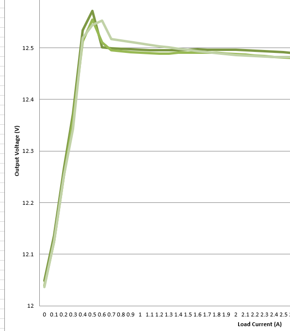
There are always a at least 500-600mV jump when no load to PSM on 12V buck.
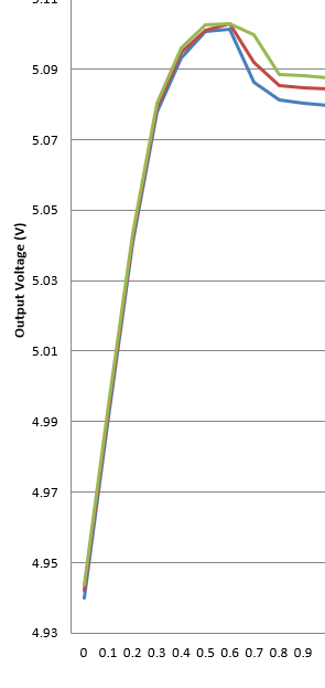
While there is around 130-150mV jump on 5V buck.
This suggesting MP4470 could suffer higher erro along the output voltage increased.
Update:
It is clear that the ramp2 configuration can be a bump on the PSM and smooth line load regulation on CCM.
But no matter how you tune the ramp voltage the issue all lies on the PSM.
You can tune the CCM back to the middle of the jump but light load error are huge and completely abnormal.
Support:
And the ramp capacitor C4 on DCDC Designer is 10 times larger than the MPS COT computation document. Please guide and explain what do the C4 impact when it is within the range of the requirement. Hences R4 impact as well.
Bests,
Brian
Hello Brian,
The function of both C4 and R4 make up your reference ramp signal to ensure that your Feedback (FB) Pin signal ripple is in phase with your Inductor Current. Please observe your signal over a longer period to ensure that your ripple is within your desired specifications.
Since you are getting repeated output spikes at different voltage levels, my first debugging inclination based on these spikes could possibly be due to a slight inrush behavior since this just happens at the beginning of your signal from what is shown. Assuming this is actually the issue, increasing capacitor C6 would help dampen these voltage spikes. See page 11 of the MP4470 Datasheet for soft start capacitor sizing. There are also more details on R4 and C4 if needed on page 10.
However, if this does not solve your issue, please reach back such that we may explore this issue in higher detail. Hopefully this helped.
Best,
Krishan
Hi Brian,
I am continuing helping you solve this problem. Please read the message I sent you.
Best,
Fox
@Krishan.FAE
Theory of soft-start is not related to the current issue. According to my weak and limited understanding on switch mode power supply. SS is just a method to reduce current on the start and make things easier.
Soft-start:
- If too long start up lock out.
- If too short in rush current might break things
So when the SS is within the MPS suggestion range cannot see this is the case.
Meantime, SS only take effect before the voltage feedback loop target is might.
So in either PSM or CCM there is no place of SS circuit to affect the final output voltage.
As for the ramp capacitor and resistor.
Why I am asking these questions are because the DCDC Designer is suggesting 10 times capacitance higher than a workable and stable system. Hences the resistor need to be adjusted as well.
It feels like MPS is having real trouble on this MP(Q) 4470 product.
Bests,
Brian
Hi Brian,
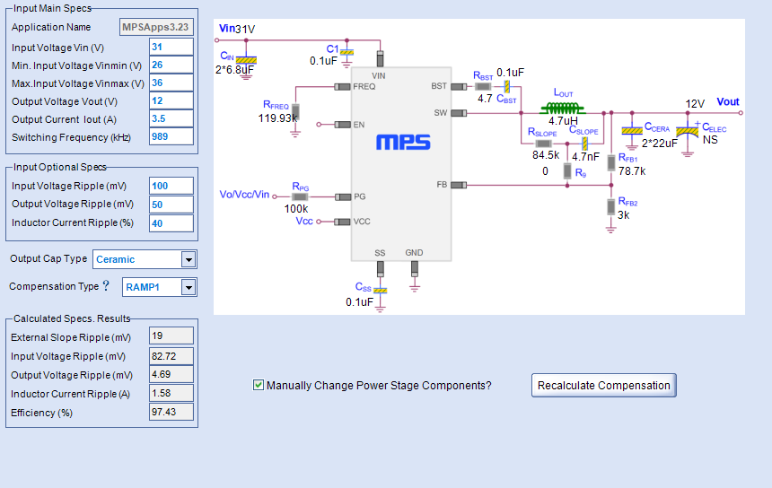
We could provide a solution for you, and we have done some related test, test result shows it is relatively stable, the sch is as shown in Fig.1, and the design index has also been given in Fig.1, the test result is as shown in Fig.2, test condition is: Vin=31V Vo=12V Io=0~3.5A, we also could see load regulation during the load change, however the change is quite limited, no more than 0.2V, which is accordance to the load regulation rate in DS.
About the questions you mentioned, it is normal to have a load regulation on MPQ4470. However the test result is quite far away from regular state. Could you give us all the detail parameters you use and the test method you use, so that we could try to replicate the test waveform then try to figure out what happened.
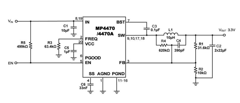
Fig.1 Sch
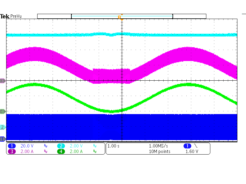
Fig.2 Test result (Vin =31V Vo=12V Io=0~3.5A CH1:SW CH2:Vo CH3:iL CH4:Io)
If you have any confusion on it, please feel to contact us.
Best,
Fox
@Fox.FAE
I will try the RAMP1 configuration of the proposed sch1.
But why only up to 3.5A?
Meantime let’s make sure we are no the same page that the computation of a COT is based on the theory document of MPS COT, otherwise we cannot sync the result.
Based on the above document, the ramp design is based on “4” major constraints.
- full load current Q 0.7 to 1.0 requirement
- Line regulation requirement
- Load regulation requirement
- R4 and C4 relationship requirement
On top of these requirement and computations, my configurations are as follow:
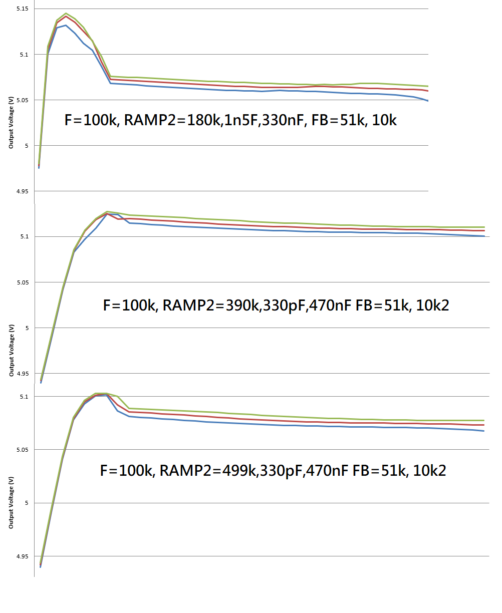
Due to datasheet and document had mentioned that DC block RAMP2 design is better on output regulation so I only use dc block RAMP2 based configuration.
5V RAMP 2 Variants
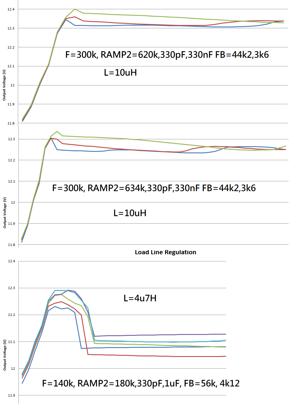
Based on the behavior of the 5V, tried to repeat the achievable result on 12V.
And inductor had increased to 10uH as we are trying to repat the EVM document result but no luck.
I can sure that if not considering efficiency other brand can have a line load regulation within 90mV. Had done test and confirmed.
Bests,
Brian
@Fox.FAE
I am still targeting a 5A solution aka MP(Q)4470.
So I am hoping MPS is going to make 4470 work.
BTW I had used MPS many product in the pass so I did not encounter issue like 4470 before.
But backup plans had been done.
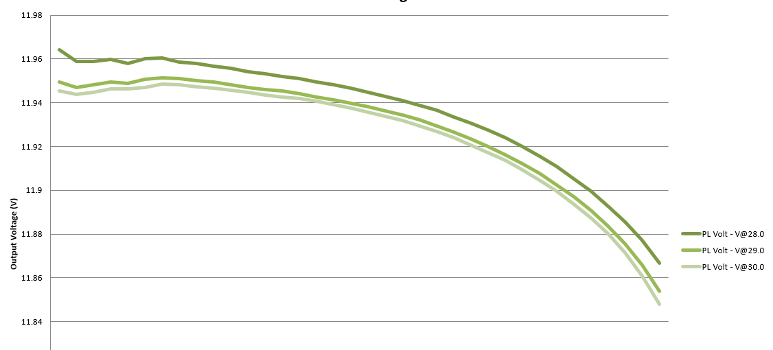
MP4430 is good and look at this beautiful result.
Of cause I am going to tune up a bit the 12V feedback resistor to encounter IR drop.
Bests,
Brian
Hi Brian,
I am glad that MPQ4430 is good for you application. I will continue tracking the next tests of MPQ4470. For the below setting:
It can have good 5A/12V output. I will continue testing the parameters you give to me. When I find something new I will share the results with you.
Thanks for all the tests you did to help us. Hope everything is well.
Best,
Fox
@Fox.FAE
What layout you are using? EVM?
What output MLCC you are using please give a very clear part #.
Do you have series of load and line regulation curve to prove the 12V 5A is good on the voltage and current band?
I had tested but no luck cannot see it can converge after 800mA drop out and lock out immediately.
Bests,
Brian
@Fox.FAE @Krishan.FAE
Hi Fox,
I had made a new batches and board routing is adjusted a bit.
New chip also used instead of reusing old batches.
I followed the schematic value you had proposed.
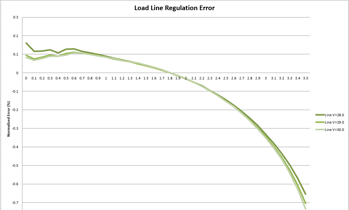
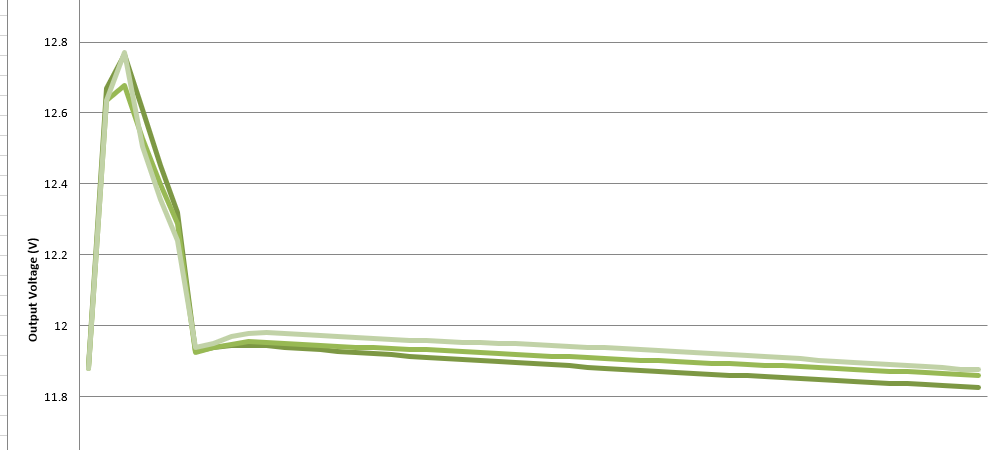
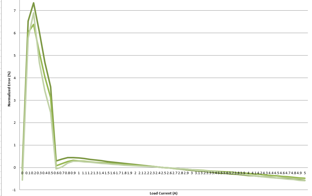
Here is the result very puzzling and unable to explain the behavior.
You can see the bump can reach up to 1V and 7% of error. Other range is very good and within design requirements.
I have no clue why MPS is having such puzzling COT buck design.
Do MP(Q)4470 have FCCM version?
Bests,
Brian
@Krishan.FAE @Fox.FAE
I am still pending on the news of the cross checking and the test result.
Bests,
Brian