We are seeing a strange issue where the output shuts off for approx 100ms under fairly light load conditions, only at certain input voltages.
Output is set to 8.4V, nominal input 12V. While testing with a load resistor of 5 ohms (ie. 1.68A), I found that as I varied the input voltage, the output would randomly shut off for ~100ms, between input voltages of 11.81V and 11.89V. Another board tested shut down between 11.75V and 11.90V. Out of 10 PCB’s produced, 4 exhibited this behavior.
We can temporarily stop this behavior by applying freeze spray. Though I don’t believe it is a thermal issue, as 1.68A is well under the 5A/6A the device is rated for, and the case temperature measured only 40-50 deg C.
We’ve inspected for soldering issues to rule this out too.
Touching the feedback network or 39pF capacitor also stops the behavior and the device operates normally. Thus I suspect it is an instability issue.
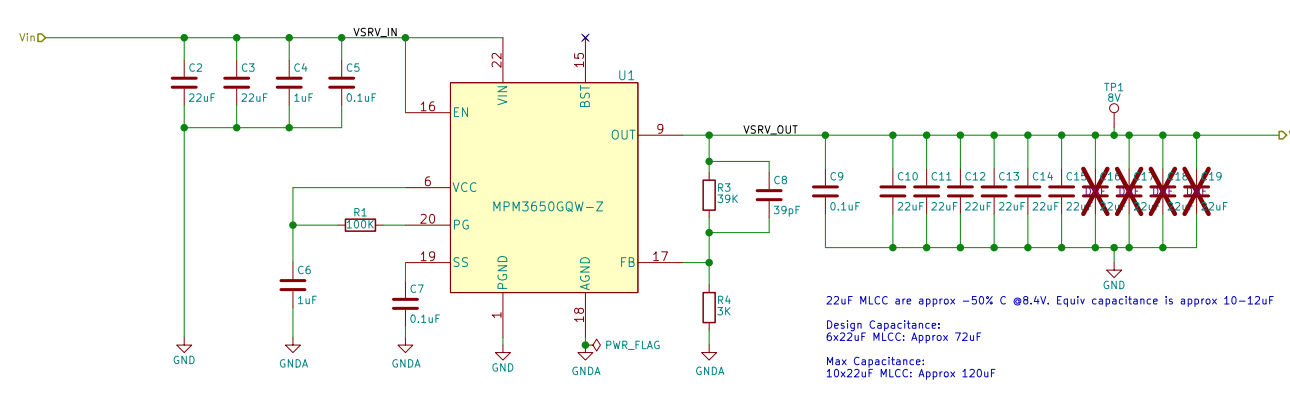
Our feedback network consists of 39k between OUT and FB, and 3K between FB and GND. 39pF is in parallel with the 39k resistor. VCC is fitted with a 1uF capacitor, SS with 0.1uF.
Do you see any issue with this design?
Unfortunately I can’t simulate as the MPM3650 doesn’t yet appear in MPS DC-DC simulation software, being a new product.
Any advice you can offer would be greatly appreciated!
Thank you.
Hello danltec,
Could you try increasing the value of the R4 resistor in your feedback network? The recommended values are 2k to 100k. Maybe it is too close the 2k bottom limit for stability. If it is possible, check the current flowing through R4. It is recommended that the current through R4 is below 250uA for balancing system stability and load loss.
Thank you,
Vinh Tran
Field Applications Engineer
Hi Vinh,
Thank you for the prompt reply.
I have since tried doubling both feedback values Ie. R3 = 78k and R4 = 6k. This should bring R4 current back to around 100uA. The problem still exists, at the same input voltage range (VIN=11.80V->11.89V)
I have also tried:
- Doubling Cf from 39pF to 78pF: Widens voltage range the fault occurs to VIN= 11.75V->11.90V
- Removing Cf: No change, Fault occurs at VIN=11.80V->11.89V
- Removing C7 (soft start): No change, Fault occurs VIN=11.80V->11.89V. OFF time decreased from ~100ms to ~20ms when the fault occurs.
- Increasing the load to around 2.6ohms (ie. ~3.2A). The fault range shifts up to VIN = roughly 14V (I didn’t note the exact values sorry). Does this suggest it may be duty cycle related?
If you have any other ideas please let me know, I’m starting to run out of components to alter! 
Hi Vinh,
Please let me know if you can offer any further advice.
For my next step in the investigation, I have ordered an EVM3650-QW-00A. I’ll test the EVM under the same conditions and see if I can replicate the behavior. If I can’t, I’ll remove one of the MPM3650 devices from my board and fit it to the EVM to see if the behavior follows the device. This should let me know if there is an issue with my design, or if the component has sustained damage somehow.
Hi Vinh,
Just another update…
I have replicated the fault using the MPM3650 EVM, to eliminate design factors. The only modification to the EVM were the necessary changes to R3 and R5 in order to set the output voltage to 8.4V.
The issue occurs between VIN= 11.87 --> 12.30V on the EVM, with a ~5ohm load.
Hello danltec,
I apologize for not replying. I was not getting an updates for this post. I will need a couple days to get back to you regarding this issue.
Thank you,
Vinh Tran
Field Applications Engineer
Hello danltec,
Is it possible for you to use an electronic load to do your test? It looks to me the device is in hiccup mode. This occurs during OCP or SCP. Your load current is too low to be OCP. However, you are using 5ohms to create 1.68A. I wonder if the 5ohms is some how triggering SCP. I don’t know why only at a certain voltage though. The hiccupping theory makes sense to me because when you removed Css the period got shorter. There is a tss between each hiccup.
Can you measure the the voltage at the pins of the device to check if Vin is as said on the on the power supply. Maybe the voltage drop on the cables
Can you measure the fsw of the device under working conditions and the bad condition?
Thank you,
Vinh Tran
Field Applications Engineer
Thanks Vinh, I’ll try to test with an electronic load and report back in the next couple of days.
I agree it appears to be hiccupping. The device “knows” it’s shutting off the output, as the PG line drops low as the output shuts off.
I’ll also try alternative input power sources, although I don’t believe there is an issue there.
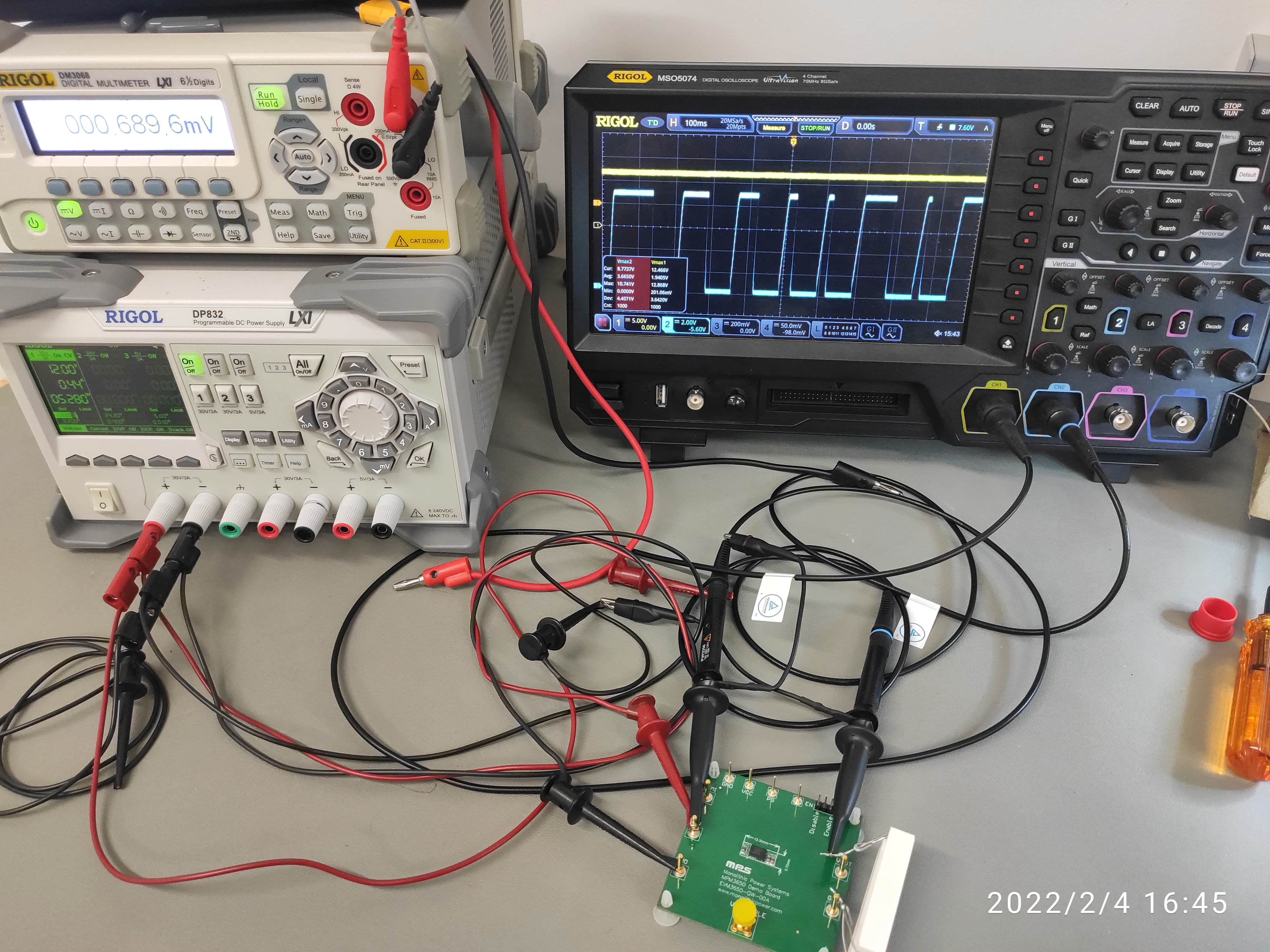
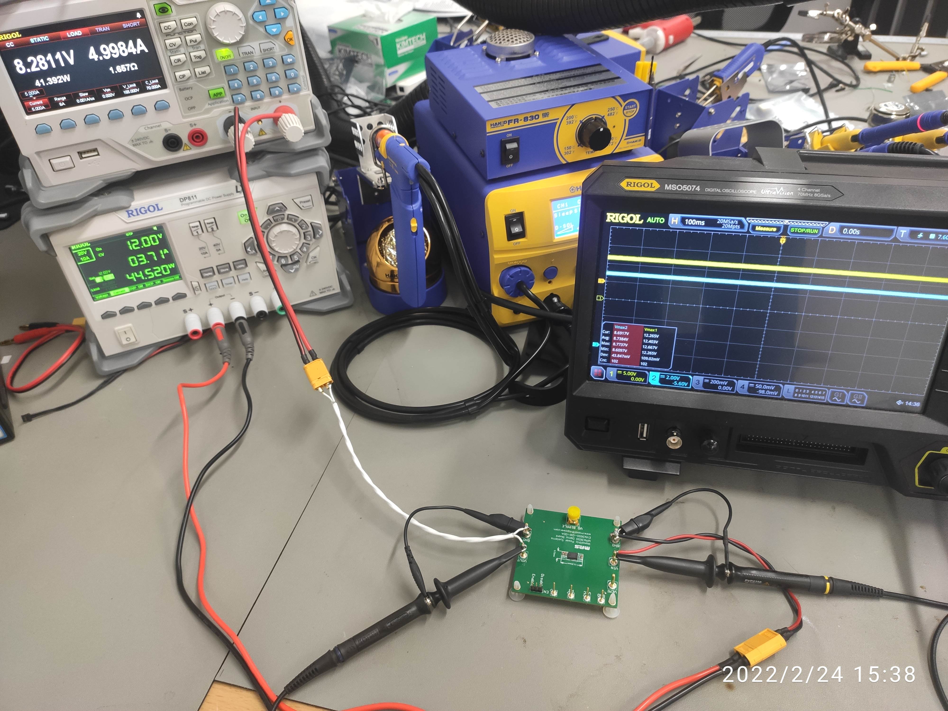
I have previously observed the input power… in the oscilloscope image above the Yellow/Ch1 trace is the input (granted, it’s difficult to see in the small image). It’s holding steady at a little over 12V.
This device doesn’t have a pin on which the fsw appears, as far as I’m aware. Is there another way to check this?
Hi Vinh,
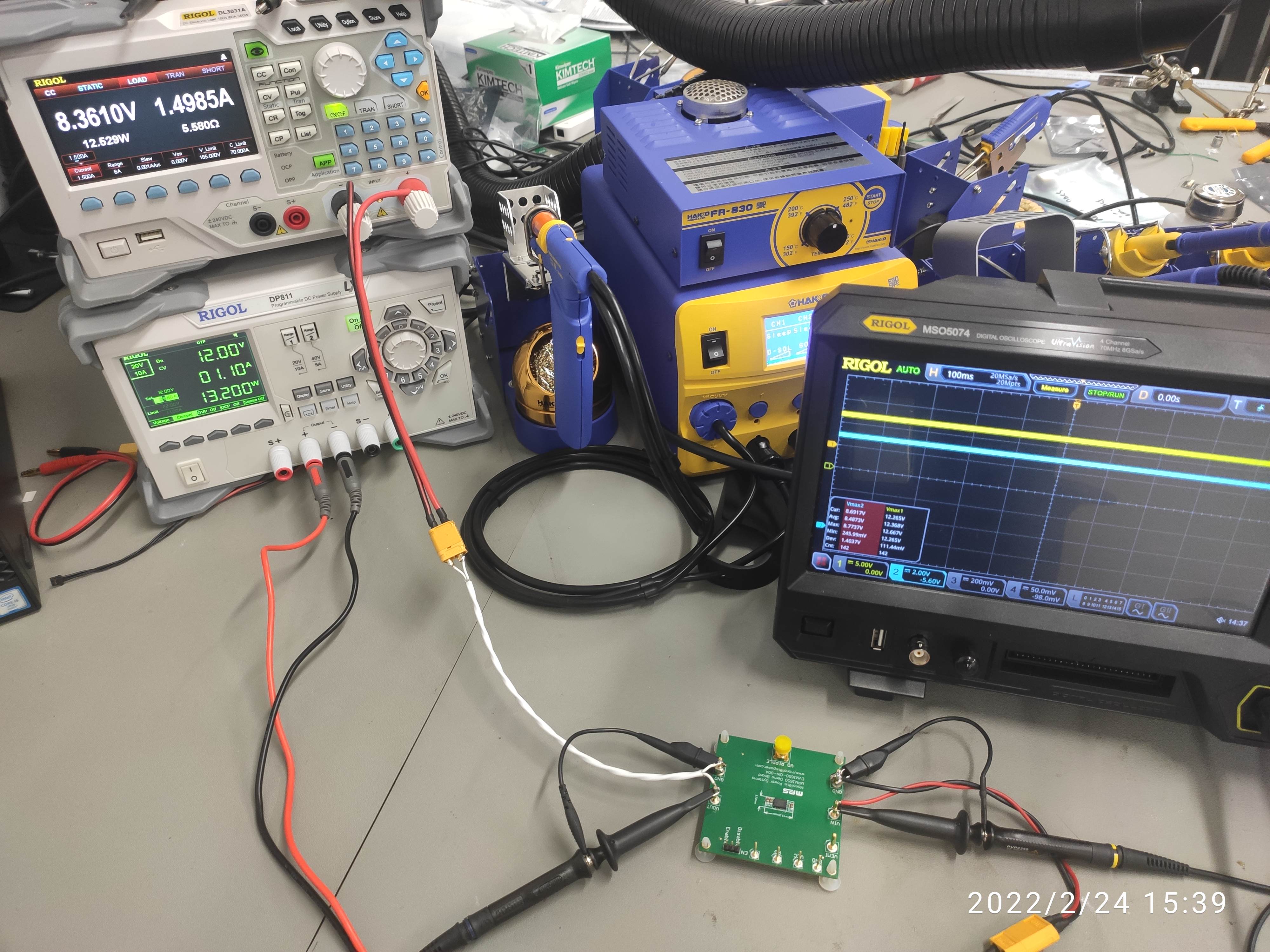
I repeated the test with a different power supply (@12V), different cables, and an electronic load.
Oscilloscope:
Yellow/Ch1: Input Voltage
Blue/Ch2: Output Voltage
Up to 1.5A, the output was stable:
At 1.6A, up to about 2A, the output was hiccupping:
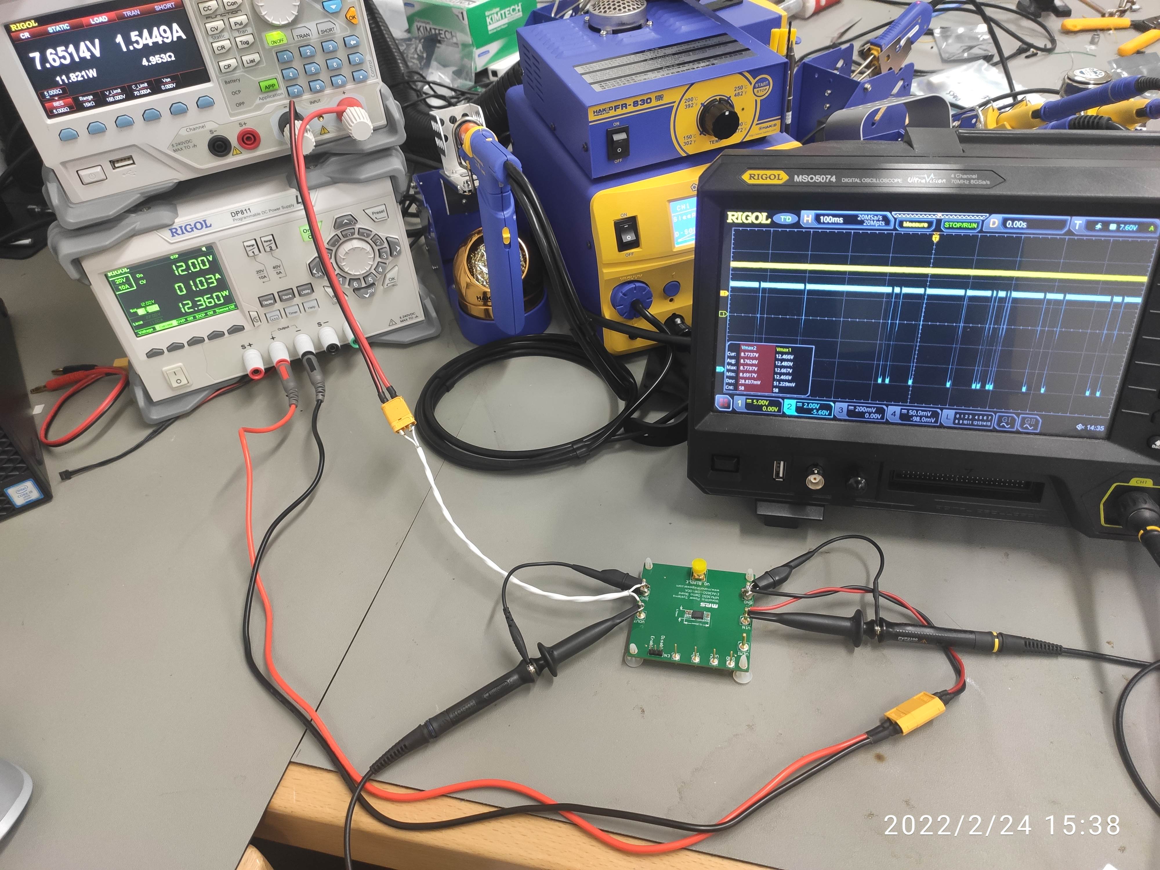
Note that I had to run the electronic load in “Constant Resistance” mode for this particular load point, as setting it to constant current @1.6A caused the MPM3650 to switch off its output permanently, and thus I couldn’t capture the behavior in an image easily.
In all other cases, the load was set to constant current mode.

Hello danltec,
It is very strange to me that it shuts off only at ~1.6-2.0A, but not at the higher currents… I will need to check with the PL. This will take a couple of days.
Thank you,
Vinh Tran
Field Applications Engineer
Go get a resistor, they don’t have fancy control loops.
Waiting for answer
resistor not working too
Hello all,
An update to this question. I will be getting an EVM to test myself. If possible could you provide SW node captures?
Can you try with R3=20k and R4=1.54k?
Thank you,
Vinh Tran
Field Applications Engineer
Thank you Vinh.
I can’t try SW node captures as this device has an integrated inductor, SW node is not available externally.
I’ll aim to try the altered R3 and R4 values in the coming week. Please keep me posted on your progress too.
Hello danltec,
There are SW node pins you can measure from.
Thank you,
Vinh Tran
Hello danltec,
Just an update on this. I have been able to recreate your issue on my end. Still trying to figure out what is causing this issue.
Thank you,
Vinh Tran
I have the same problem.
With 12V input and 5V output, the shutoff is about 14mS with about 3A load.