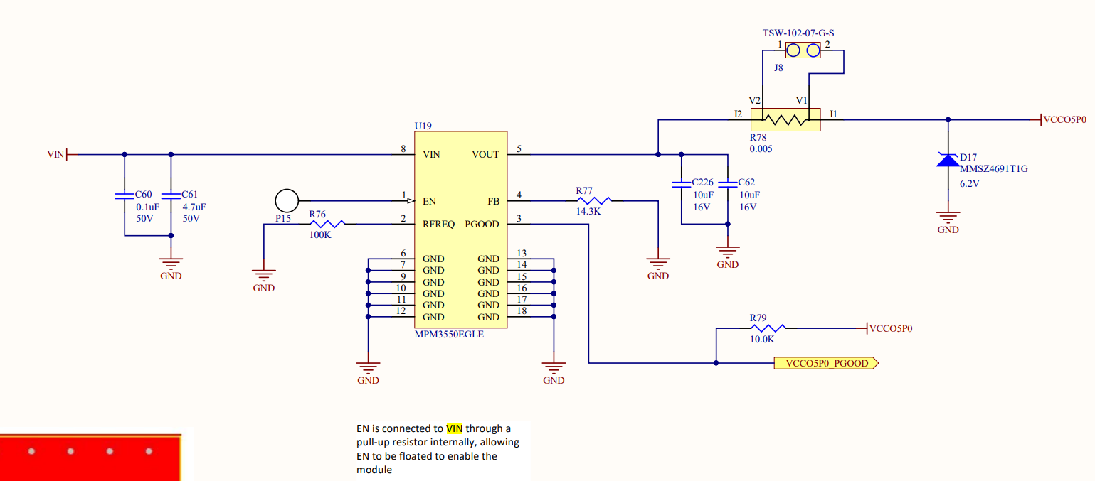
I’m having trouble bringing up a board with the MPM3550E module. I have 12V as the VIN value and I am adding the 14.3K ohm pull down on the feedback pin for setting the VOUT to 5V. The layout follows your suggestion in the data manual for the part. I measure the resistance between FB and VOUT to expecting the 31.6K in the data sheet but I only see about 8K. The pin one indicator on the package (a small hole) is in the correct orientation on the layout. When I apply 12V to VIN I get around 0.8V on the output and some kind of liquid begins bubbling from the pin one indicator. I’ve attached the schematic and the top layer of the layout. Do you see any issues with the way it is implemented? Should I be able to measure the resistance associated with the feedback resistance as shown in the data manual?
Hello bill.taboada,
Your schematic looks fine to me.
The bubbling liquid is kind of strange. Was this a hand solder job? Is it possible that some pins may have been shorted?
Please verify that all connections are solid. If it is possible, please remove the device and check that there are no pins shorted.
Can you try replacing the chip to see if the correct operation is seen?
Thank you,
Vinh Tran
Hi Vinh,
This is the LGA-18 package so inspecting the connections isn’t really possible. I suspect that the liquid may have been due to the cleaning process at the assembler. I didn’t realize that the pin one indicator is actually a hole in the top metal cover. I am concerned that the can filling up with some solution may have caused an issue.
Some additional questions,
1 - I have a pullup on the power good circuit and a review of the data sheet leads me to believe that isn’t necessary. The internal diagram shows a pull to the internal VCC. I removed that resistor but didn’t see any change in the behavior.
2- As I stated, I’m concerned that some liquid got under the cap during cleaning. Are there any special instructions for assembly for this part? Should they be have the hole covered to avoid this?
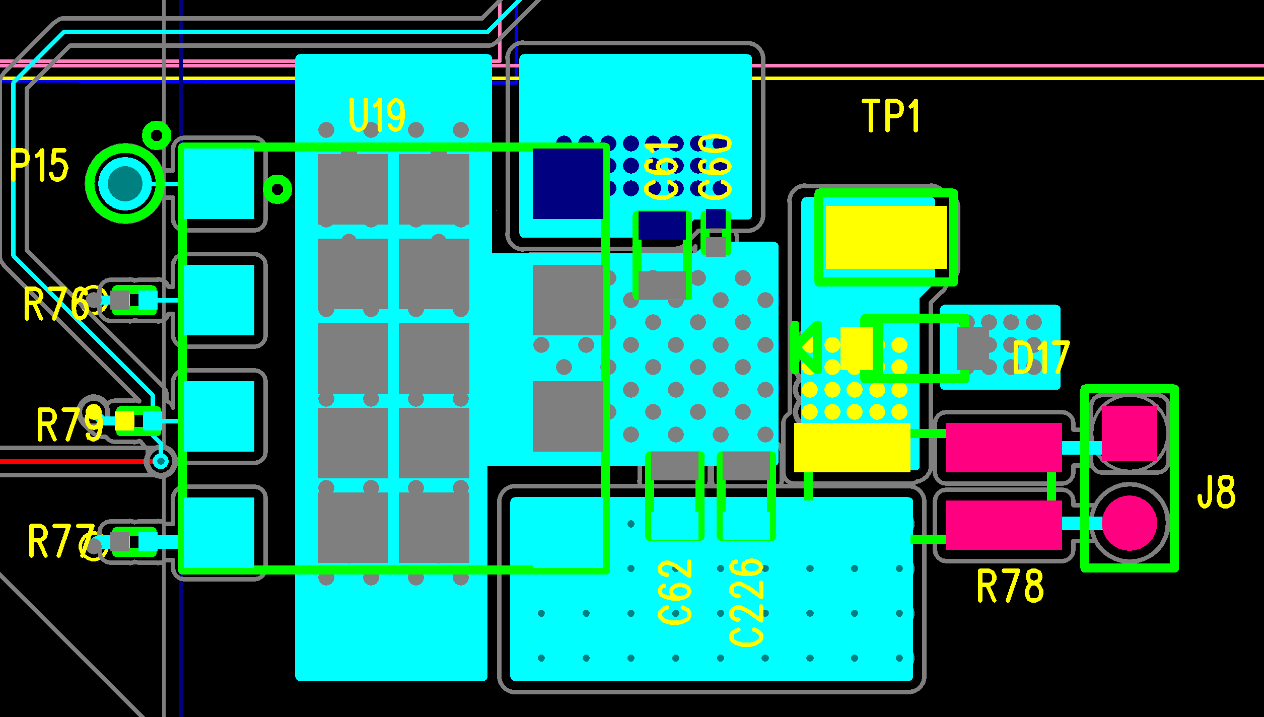
3 - I’ve attached an image of the PCB top layer. It matches the recommendations pretty closely. Do you see any issues?
4 - I measured the output voltage on a scope and I see it start to rise quickly until it gets to about 3V then it ramps down more slowly to a level before rising quickly again. This resembles a sawtooth. It almost looks like the circuit is going into a thermal shutdown, cooling off and then restarting. I’m not feeling any heat on the cap. Does that provide any clues?
5 - I’ve submitted a request for a call. Hopefully that happens soon.
Thanks for the quick response.
Bill