MP9486AGN-Z - start-up issue

Hi,

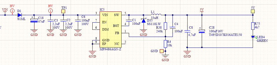
I have seen multiple threads on this forum regarding MP9486AGN lock-up / start issues, but no real resolution or detailed explanation. We had some similar issues at the beginning, approx. 2-3 years ago while also having issues with badly regulated output voltage when Vin>60V. But later after we removed additional output capacitor and replaced electrolyte one with tantalum type, start-up issues were not detected. Schematic follows evaluation board/reference design.

We made 1000+ devices, with no major issues or at least we did not detect them. But now, in our last production batch, we have multiple devices with this issue.

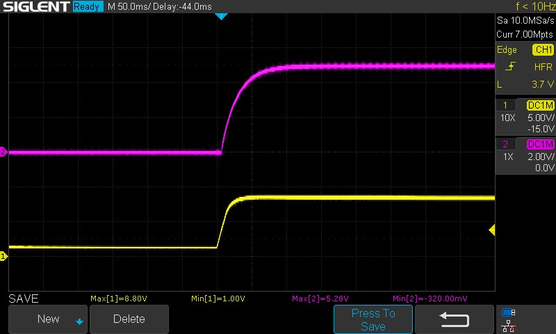
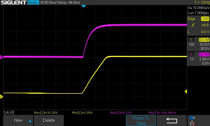
We have two models of electronics - one without LTE modem. This one works just fine - charts as shown in datasheet. You can see attached ramp up of power supply (Yellow) and output voltage (5V-purple). First at VIN = 10V, second VIN = 32V. No issues here.


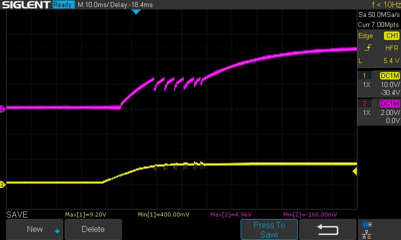
Second product - with LTE modem, has compared to above one additional switching buck converter. Typical working board performs like this. I can see a few dips t the beginning (due to inrush current) while caps are charging, but switcher starts and works.

Some boards behave like this. Similar to above, but after two or three dips, switcher locks somewhere in the middle and does not recover. What is even more strange, some boards show this issue at 10V, and work when connected to 32V, while others work at 10V, but not at 32V. Manually you can sometimes recover from that state if you do the same as described here - but this is not a solution for our use case (MP2456GJ-Z Startup problem).

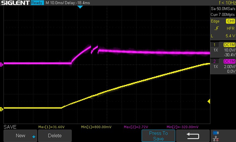
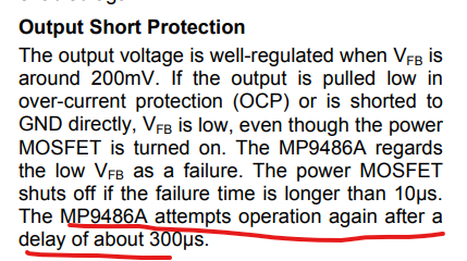
In case of lock-up state, feedback pin is like this - yellow - obviously SCP is triggered.

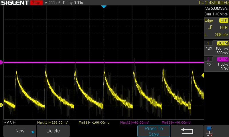
I will try to measure peak output current but this will not be an easy task, since PCB board is not made in this way due to use of polygons.

Any suggestions, what to do to improve start-up stability?

Hi Simon,

Sorry to hear that you are facing issues with MP9486A. The schematic looks good overall.

I think this could be probably a soft start problem for the the dips and trigger you are seeing.

Can you check if it is working with a bit larger value than 33uH, for example 47uH, 68uH?
The idea behind this would be slowing down the start-up process a bit and eventually preventing inrush current spikes.

If you are seeing a badly regulated voltage, then I would suggest adding a one more ceramic capacitor of any value between 4.7uF ~ 22uF of either 0402 or 0603 package.

image

Let me if that works for you or not or if you have any more questions on it.

Regards,
Adhish

Dear Adhish,

It took a while to come back to this topic.

I have replaced the inductor with 47uH instead of 33uH and issue is partially resolved. I have tested 3 boards. Two boards, now work up to 32V (I will later try with higher voltages). Before, they did not start at all. You can see a few dips at start-up, but switcher starts. The third one works well up to like 24Vin, but above that, similar issue exist. Switcher hangs.

Now I am wondering, if we increase the inductor value even higher to 68uH, what is the expected outcome? As you said, slower start-up process, but can anything else happen? Is there any other risk?

Thank you for your help.

Hi Simon,

Good to know that the two boards are working fine with 47uH.

Let me recall somethings from the last discussion:

  1. What is your end product application ? Is LTE Modem the output load for your application? Or is it the input to MP9486A?
  2. What is your load current? Are you seeing such behavior during full load?
  3. When you say the 3rd board is not working beyond 24Vin, is it hitting any protection or fault limit? Is the schematic same as the previous 2 boards?

Regards,
Adhish

Hi Simon,

Missed out your inductor question in my earlier response:

As the inductance gets higher, the converter is more sensitive to noise, and you may see jittering switching waveforms. The ripple current through inductor will be reduced with higher inductor. So it’s easier for non-sync part such as MP9486A to operate in CCM instead of DCM at light load. This can result in:

  1. Lower ripple voltage on the output
  2. Better conversion efficiency at light load or reduced power loss at no load.

However, larger inductance may cause some stability issues or inductor current overstress problem under certain fault conditions. It’s strongly recommended to recheck the stability and the Energy Handling Capability of Core when going with high inductance.

So based on this, at what switching frequency are you designing the buck?

Regards,
Adhish

Hi Adhish,

Good to know that the two boards are working fine with 47uH.

Yes, two boards are now working up to 32V (where with 33uH they did not), but above 36V, the issue remains. Meaning, I may try increasing inductance to 68uH, but my concern is - to where we can go before we hit any other issues. We really need reliable solution.

The third board, now works up to 24V, but not above that. All three boards were populated within the same batch - so they have the same schematic and components from the same batch. With previous batch, we did not experience similar issues, but schematics was pretty much the same.

  1. What is your end product application ? Is LTE Modem the output load for your application? Or is it the input to MP9486A?

LTE Modem is the main output load. But it is not all about the load. Even if I disconnected all power hungry parts, board performed the same. It did not help much, maybe a bit.
End application is some kind of a logger device for the battery (different batteries, ranging from 12V to 80V+).

  1. What is your load current? Are you seeing such behavior during full load?

We have only seen this issue during power on / start-up of the board. I have even tried putting 1-10R resistor in series with the load, with no improvement.

  1. When you say the 3rd board is not working beyond 24Vin, is it hitting any protection or fault limit? Is the schematic same as the previous 2 boards?

Yes, schematics is the same. Issue is with the start-up. But I have also seen a board, that worked at 12V, but when increasing the supply voltage, at first, it started to release some strange switching noises and then at some point, it stopped working.

However, larger inductance may cause some stability issues or inductor current overstress problem under certain fault conditions. It’s strongly recommended to recheck the stability and the Energy Handling Capability of Core when going with high inductance.

So based on this, at what switching frequency are you designing the buck?

How can you set switching frequency of MP9486A? We have followed your reference designs for 5V and 1A output.

Many thanks,
Simon