We are experiencing unexpected behaviour from the MP5042. The current limit is around 40 % lower than expected. Our board has two outputs with one MP5042 on each output. Rlimit is 3.6k which should result in a current limit of 148 mA. On the one board we’ve tested so far, we’re getting a current limit of 97 mA on one output (called P10) and 85 mA on the other output (called P20).
We get the same result on P10 with a 114 ohm load, an 82 ohm load and during start-up with a real load with a switched power supply. With a 114 ohm load, the current shouldn’t even be limited since 15 V would give only 132 mA which is below 148 mA minus the room temperature tolerance of 7 %.
Conditions:
- VIN is 15 V (rising from 0 V during start-up)
- C(dVdT) is 1 uF
- EN is tied to VIN via a 330k resistor
- There is a 10 uF capacitor at each output
- Testing was done at room temperature
A second question I have is about the hiccup mode described in the datasheet. It says the MP5042 will turn off its output for 90 ms if it experiences 2 ms of overload. But what is overload? In the tests we’ve done it doesn’t turn itself off until it’s been in current limit for much longer, 0.3 to 0.4 seconds in the attached images. This is a good thing for us but we would like to understand the behaviour so that we can rely on it.
Hello @niklas.angare,
Could you try decreasing the resistance until you see roughly the right current limit? could you also try testing how accurate the current limit is at 250mA with Rlimit floated and at a higher current like 500mA. This will help me figure out if this accuracy issue is only happening at small currents.
As for the hiccup mode, it can be triggered by either by a current that exceeds Ilimit, or by overtemperature. However, during startup Ilimit is used as the setpoint for the control loop to regulate the internal FETs and thus the output current/voltage. This is because it is expected that there will be capacitance that needs to be charged up at the output, so this is used to limit the inrush and charge up the caps slowly. Once the chip sees that the output is charged up then the normal Ilimit behavior begins. Try testing using load after powering on the E fuse and charging up any capacitance and see if that has any effect on the Ilimit value.
let me know what the results of testing are.
Best regards,
-Kerr
Hi @Kerr.FAE,
Which resistance did you want me to decrease? Rlimit? According to the datasheet, Ilimit is adjustable from 25 mA to 2 A, so 148 mA shouldn’t be a problem, right?
I hadn’t realized the MP5042 has different behavior during start-up and during normal operation. I don’t see this described in the datasheet. Could you point me to any information you have about this? What is the minimum and maximum current limit during start-up with an Rlimit of 3.6k?
I’m not able to make any measurements right now so I would appreciate if you could answer these questions in the meantime.
Hi @niklas.angare,
Yes, please try different values of Rlimit, this will just give me a better idea of the scope of what you are seeing.
After talking with my colleagues I want to clarify that the difference in startup behavior is not intrinsic like I made it seem. What I said would assume that the current is being limited by the DVDT functionality and not the current limit itself. That shouldn’t apply to you since you are using resistors. Try using a capacitive load to confirm this functionality and see if the internal FET is turning on completely under this condition.
Best regards,
-Kerr
Hi @Kerr.FAE,
In your second paragraph, I suppose you’re asking if the constant current we’re seeing during parts of the start-up sequence with the real load, is due to capacitors charing at a constant dV/dt. If I put 500 ohms in parallell with the real load, I get the same current level, indicating that it is in fact a current limit.
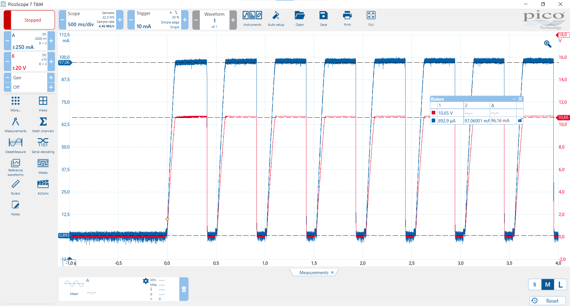
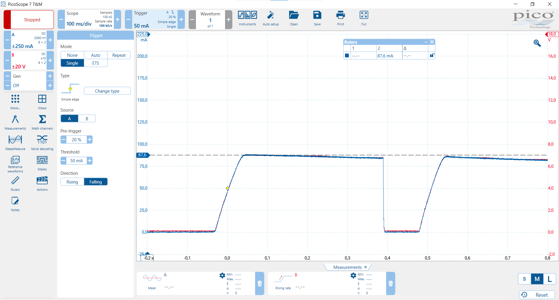
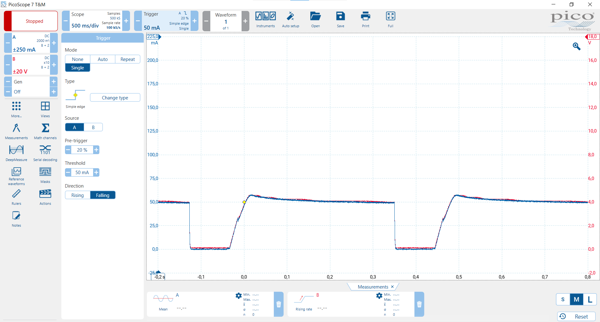
I have now made measurements with resistive loads connected after start-up. With a load resistance high enough that the current limit shouldn’t trigger, it doesn’t, which is good.
When a load is connected after start-up, with a resistance low enough to trigger the intended current limit, the current is again limited at a lower value than expected. In this case, the output is shut off for 90 ms after only 2 ms, which matches the hiccup described in the datasheet. After that it goes back to the mode where it can stay current limited for 3-400 ms.
Zoom:
(Note that when there is zoom, the ms/div at the top doesn’t reflect the time axis shown. You need to instead look at numbers along the time axis at the bottom, where the unit is given with the leftmost number.)
(The drop of a few tenths of a volt as the load is connected is probably voltage drop across the amperemeter connected between the output and the load where the probe is connected.)
Hi @Kerr.FAE,
Continued from above due to forum image limit:
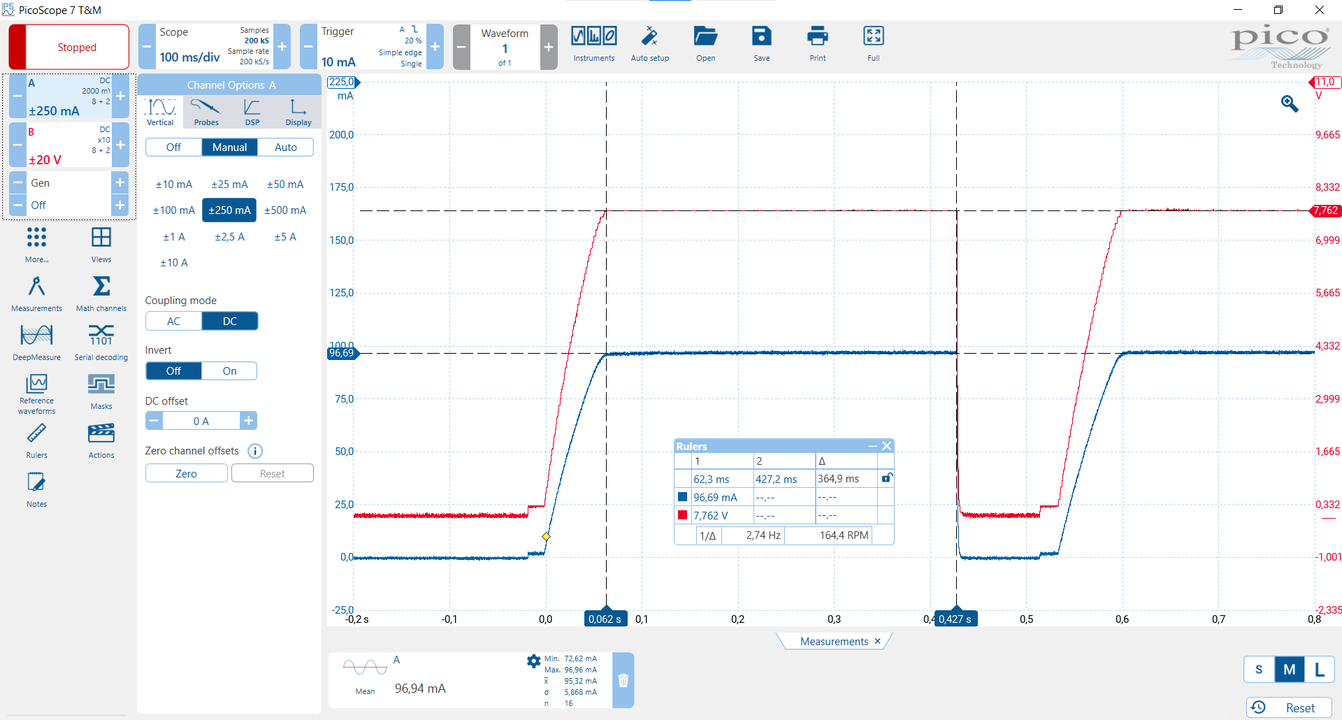
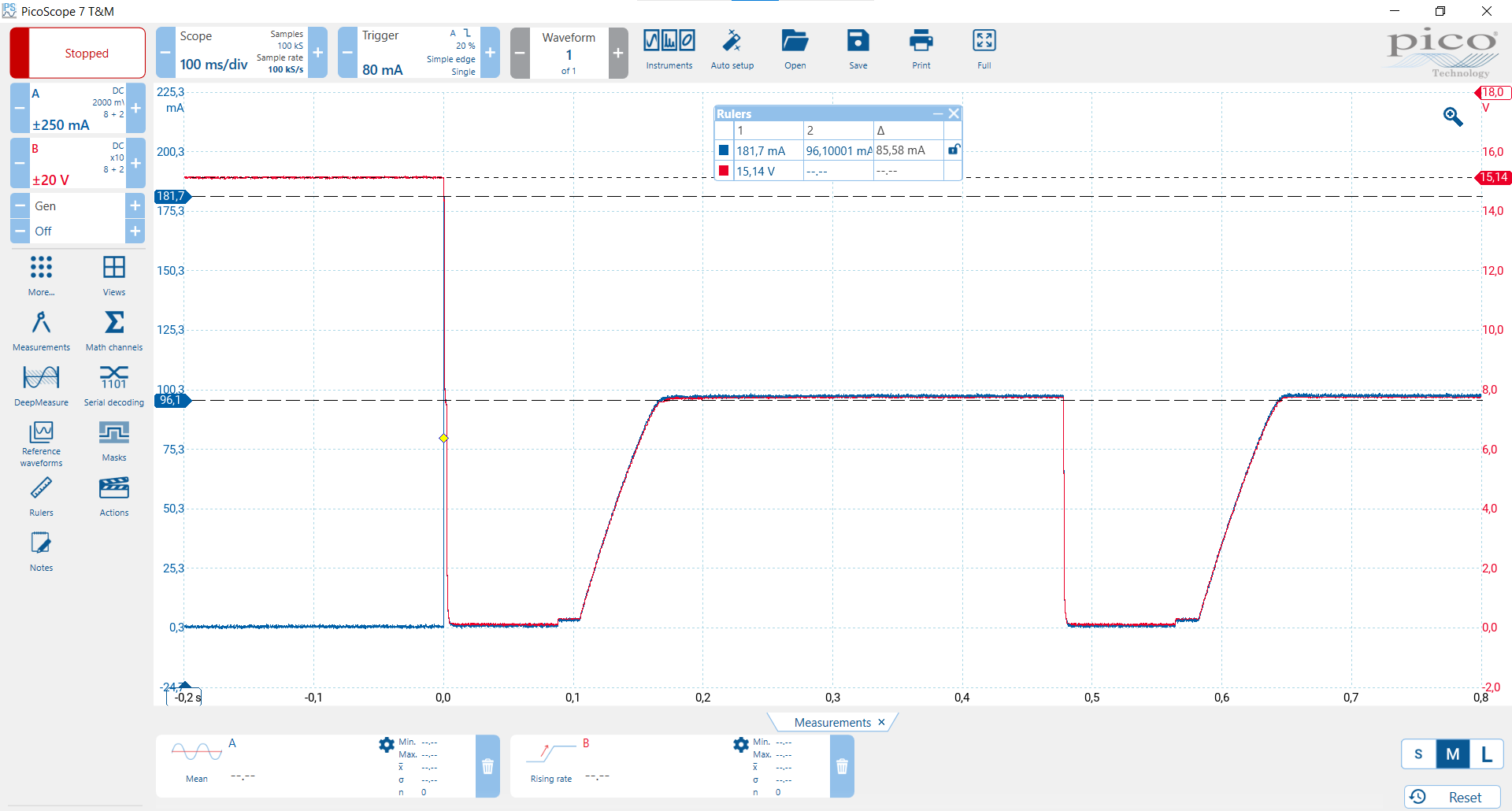
Here, 114 ohms was connected after start-up but before the measurement started, then 560 ohms was connected in parallell around time 0,0 s:
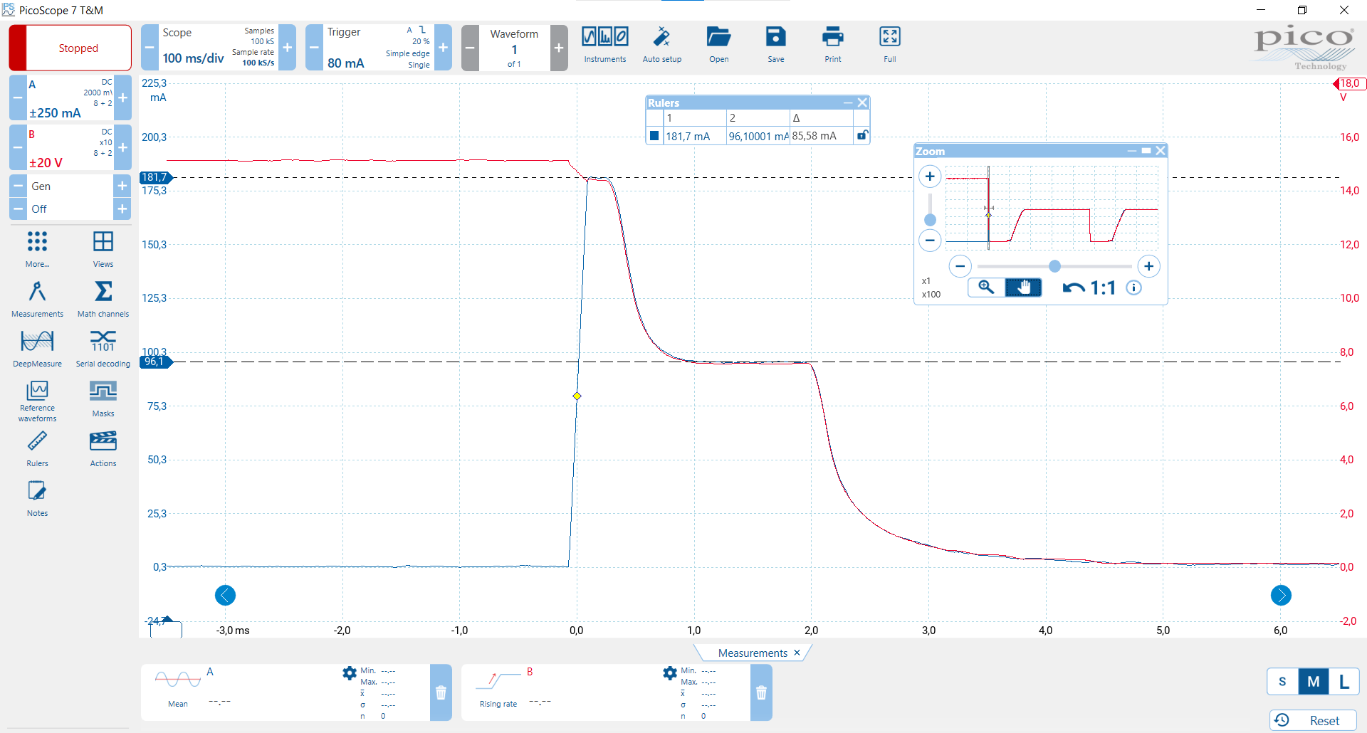
Zoom:
If, in the situation described above, the load resistance is increased to a value high enough that the current limit should no longer trigger, it still does.
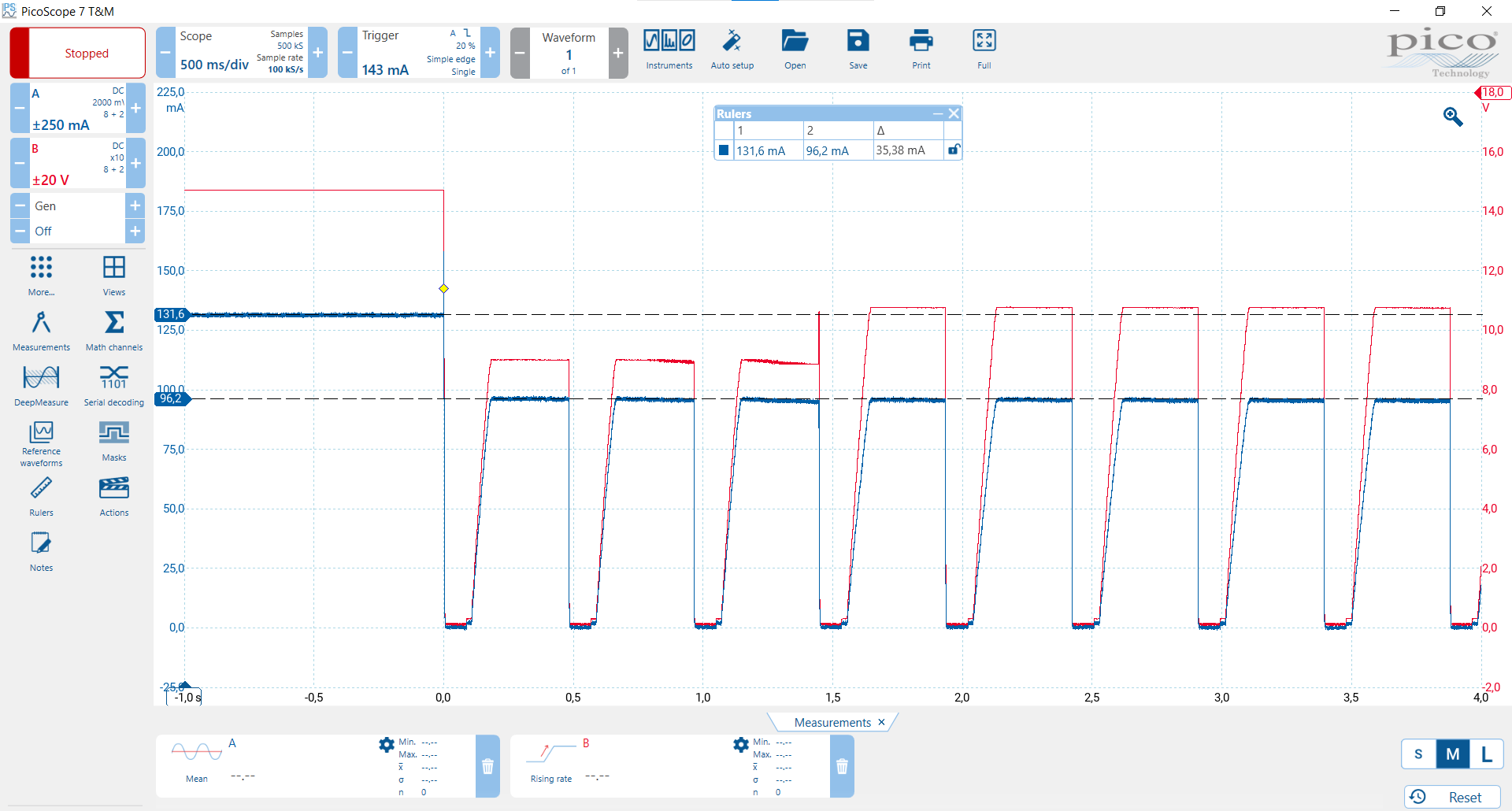
Here, 114 ohms was connected after start-up but before the measurement started, then 560 ohms was connected in parallell around time 0,0 s and then removed at around 1,4 s:
Hi @Kerr.FAE,
Continued from above due to forum image limit:
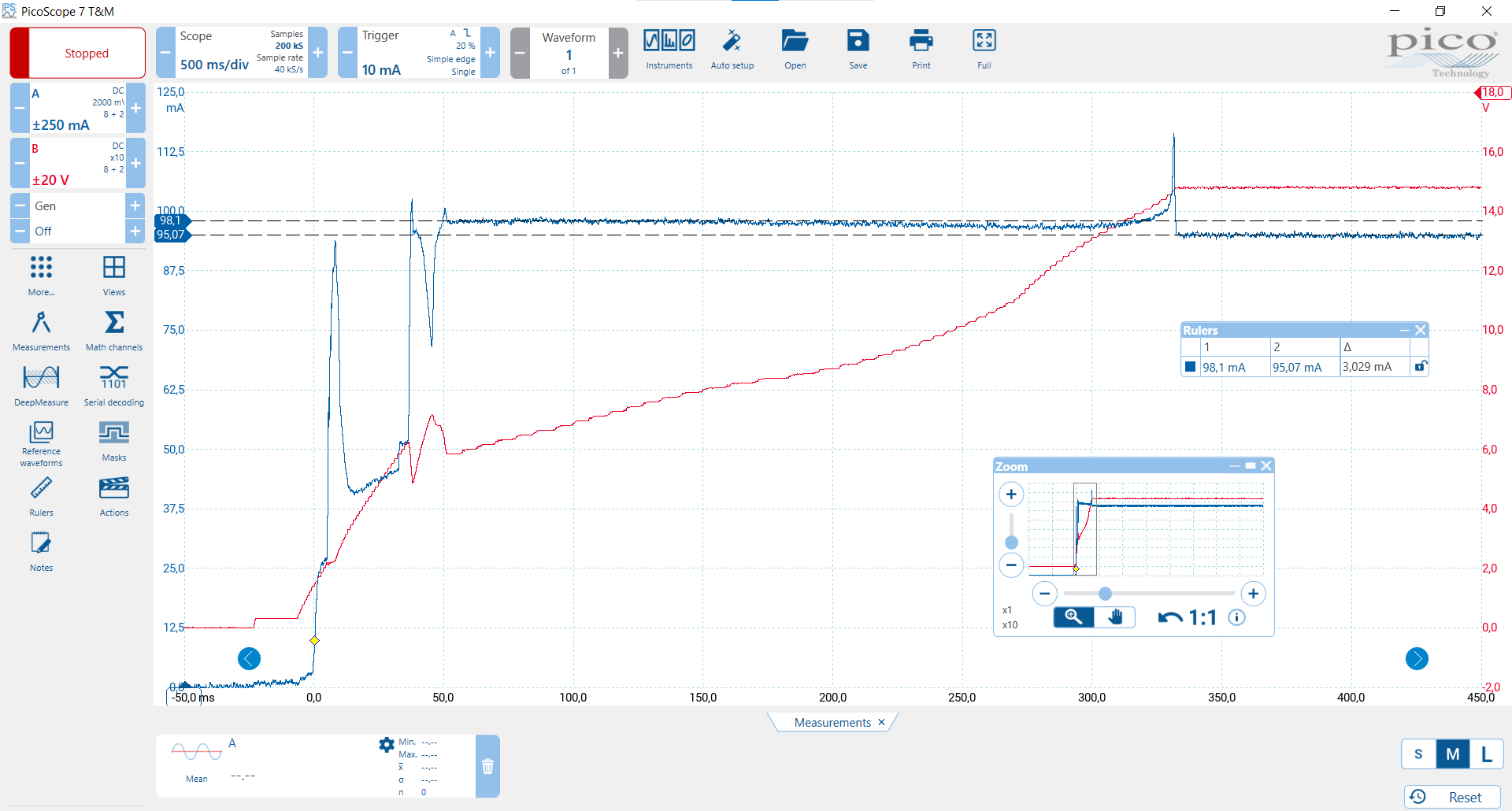
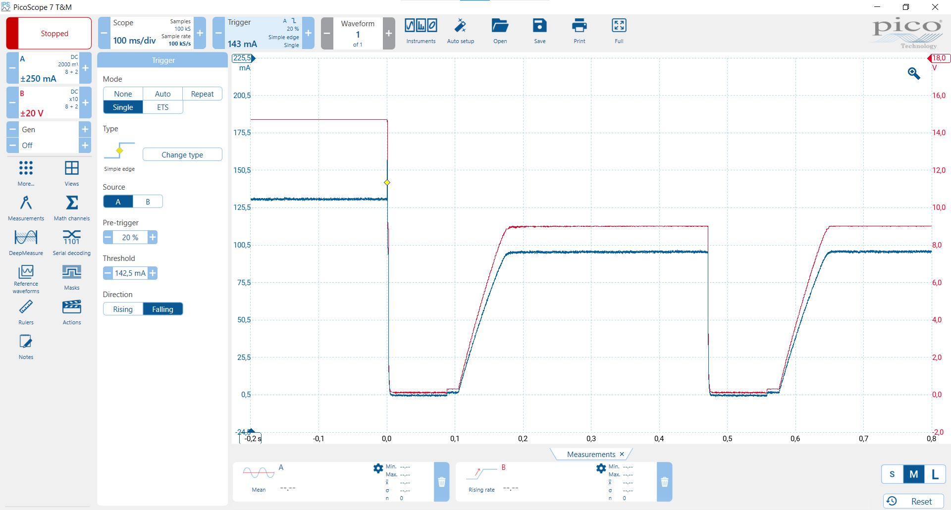
Here are some measurements with Rlimit removed:
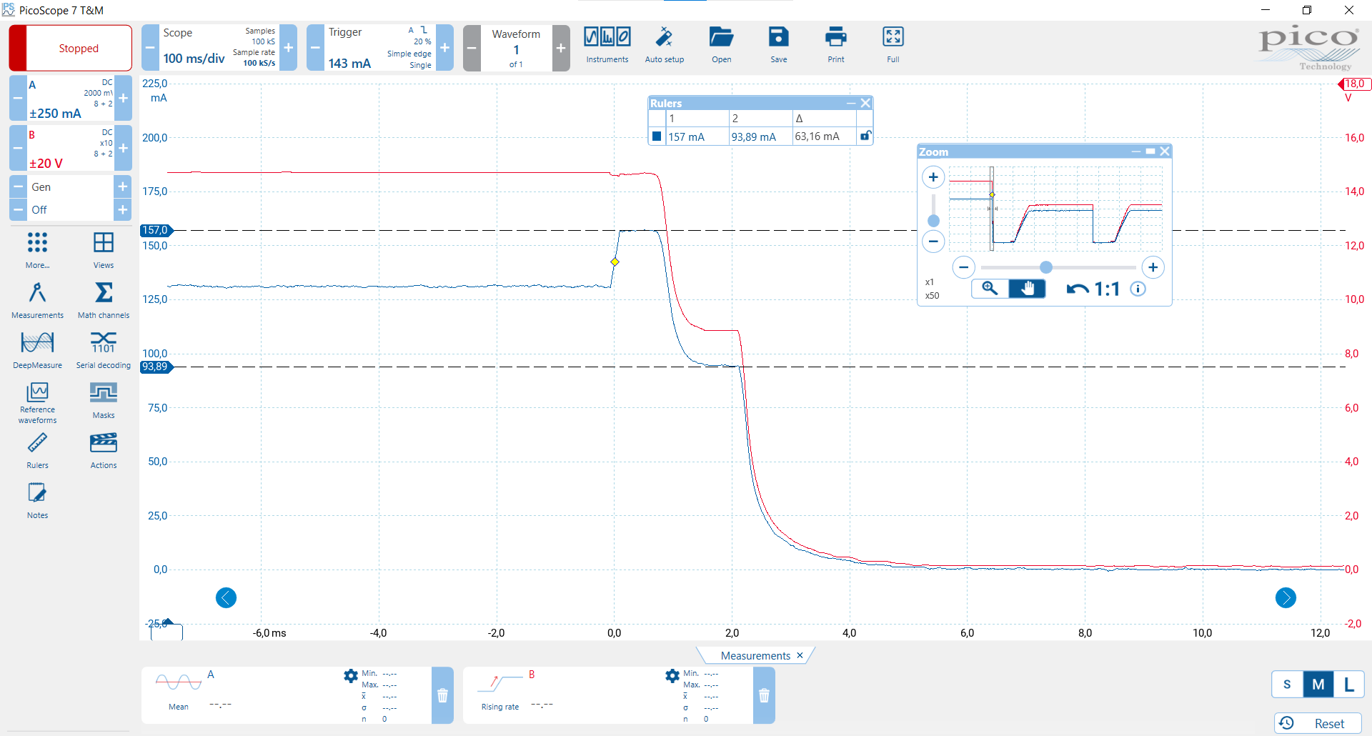
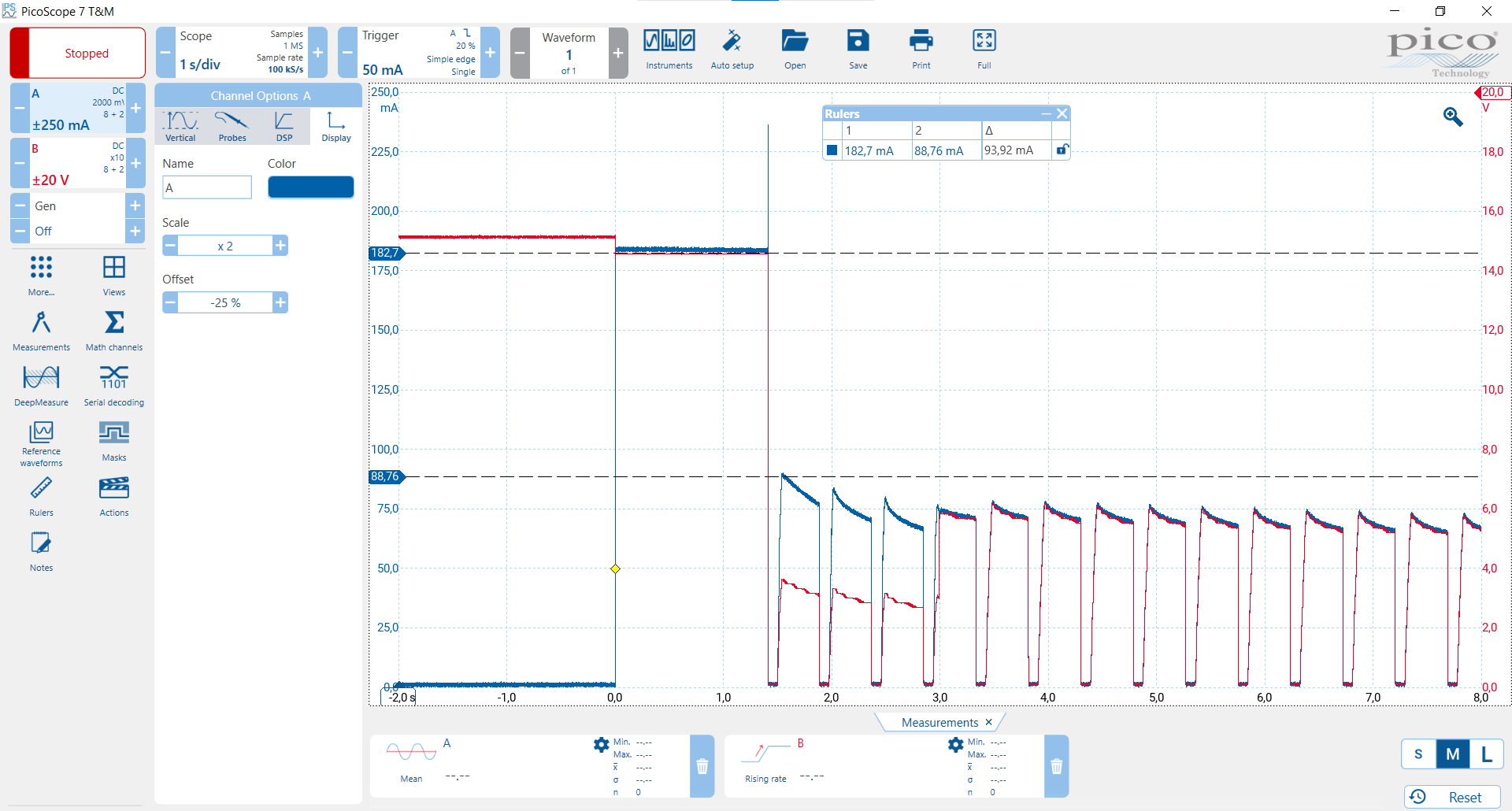
The current limit appears to go lower over time, this is later in the same sequence:
Here, 82 ohms was connected after start-up at around 0,0 s, then another 82 ohms was connected in parallell (for a total of 41 ohms) around 1,4 s and then removed at around 2.9-3.0 s:
@niklas.angare ,
I am asking around about this behavior internally. What is the intended load that this E fuse is going to be powering? Also the process you described where the current limit is lowered in this post where you say
That is called current limit foldback and it is described in the datasheet, generally it happens only when the Vin-Vout is with a certain range. Could you get a waveform capture of the Vin as well as the Vout to make sure there is nothing unusual at the input voltage that is causing this behavior? If you recreate the waveforms you captured in that post that look like a stairstep that would be helpful.
Also, try testing the current limit with the R limit being an open circuit to see if the current limit is working correctly under that condition.
Best,
-Kerr
The intended load or the “real load” as I’ve referred to it, is an LDO (with a very low drop-out and 10.5 V nominal output) followed by a device with a switch-mode power supply. There is a 100 uF capacitor on each side of the LDO. If I increase the voltage to the LDO very slowly, the switch-mode power supply starts at 5.7 V.
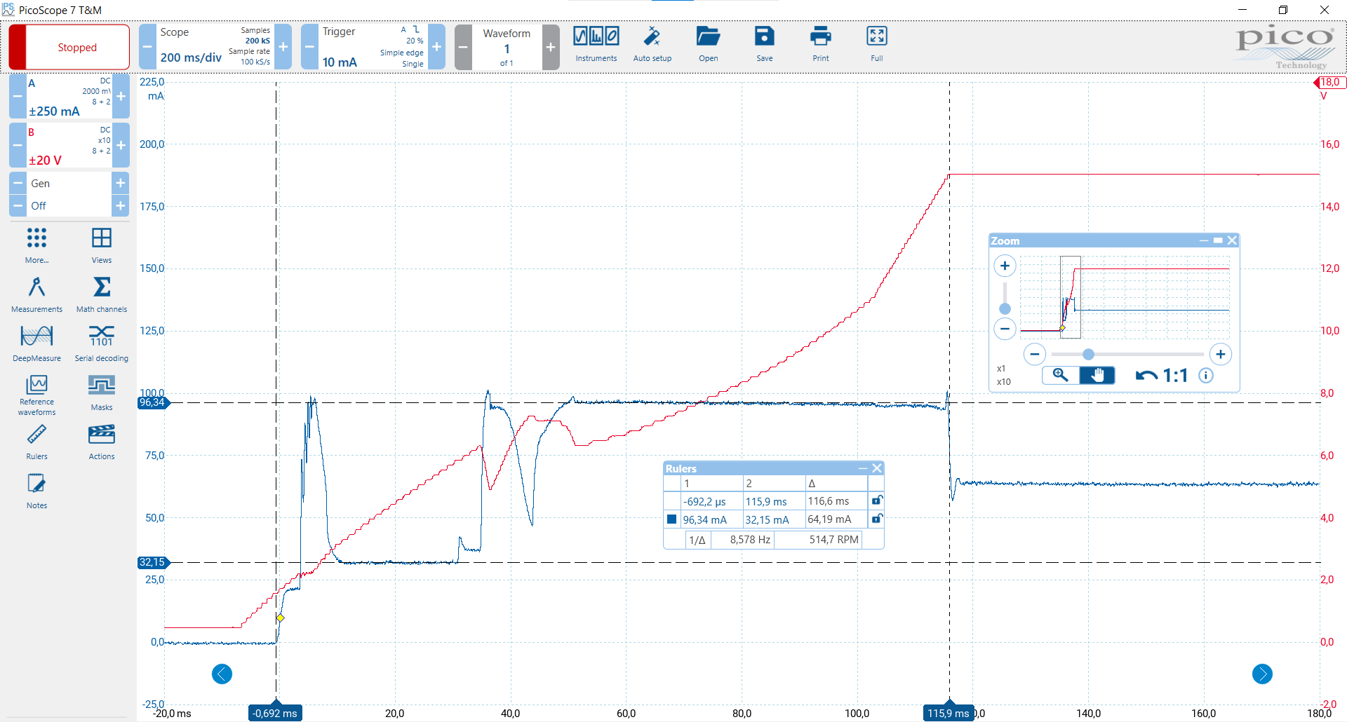
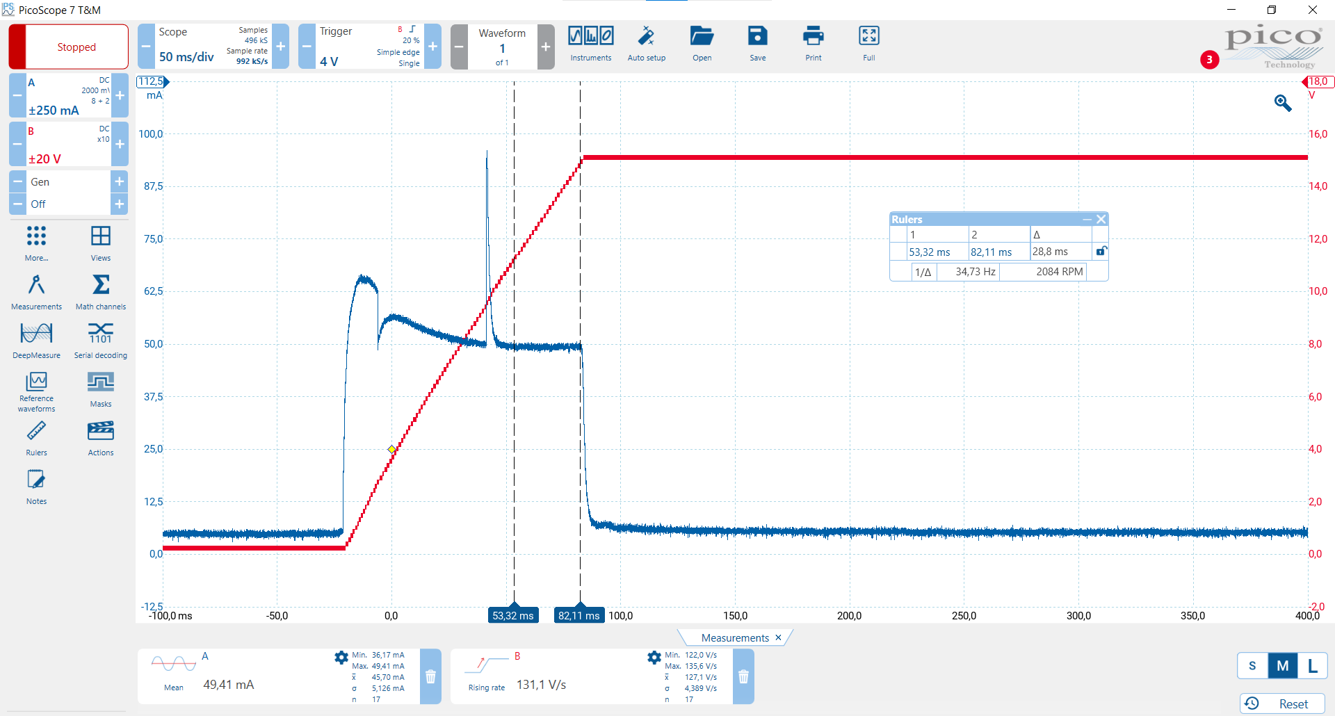
I see the following in the third image in my first post (“Real load on P10, start-up”):
- In the interval between 10 and 30 ms, dV/dT is around 133 V/s which is at least somewhat close to the expected value of 97.5 V/s with C(DV/DT)=1 uF. The current is a constant 32 mA which would match a 240 uF capacitance being charged at this dV/dt. This seems reasonable with 2x100 uF plus whatever is at the input of the switch-mode power supply.
- Then the current increases as the voltage approaches 6 V, probably due to the switch-mode power supply starting.
- Then the current is constant in the interval between 50 ms and 116 ms. It seems like the current is being limited to 96 mA, but I don’t understand why. Even when the load changes, the current stays the same. It’s the same current limit we get during start-up with resistive loads of 82 ohms and 114 ohms.
- When the voltage reaches 11 V, the LDO starts regulating which means the capacitance at its output (at least 100 uF) stops charging. At the same time, dV/dt changes to a higher value which makes sense since the capacitance effectively just got lower while the current is still limited to the same value.
Are you referring to the “three different scenarios for the hold current” in the datasheet? As I read it, since we set Ilimit to 148 mA which is below 260 mA, we should get 100 % of Rlimit regardless of Vin-Vout. Its only when Ilimit exceeds 260 mA that you would get 50 % of Ilimit in scenario 2 as I understand it. Also, 97 mA is not even close to 50 % of 148 mA.
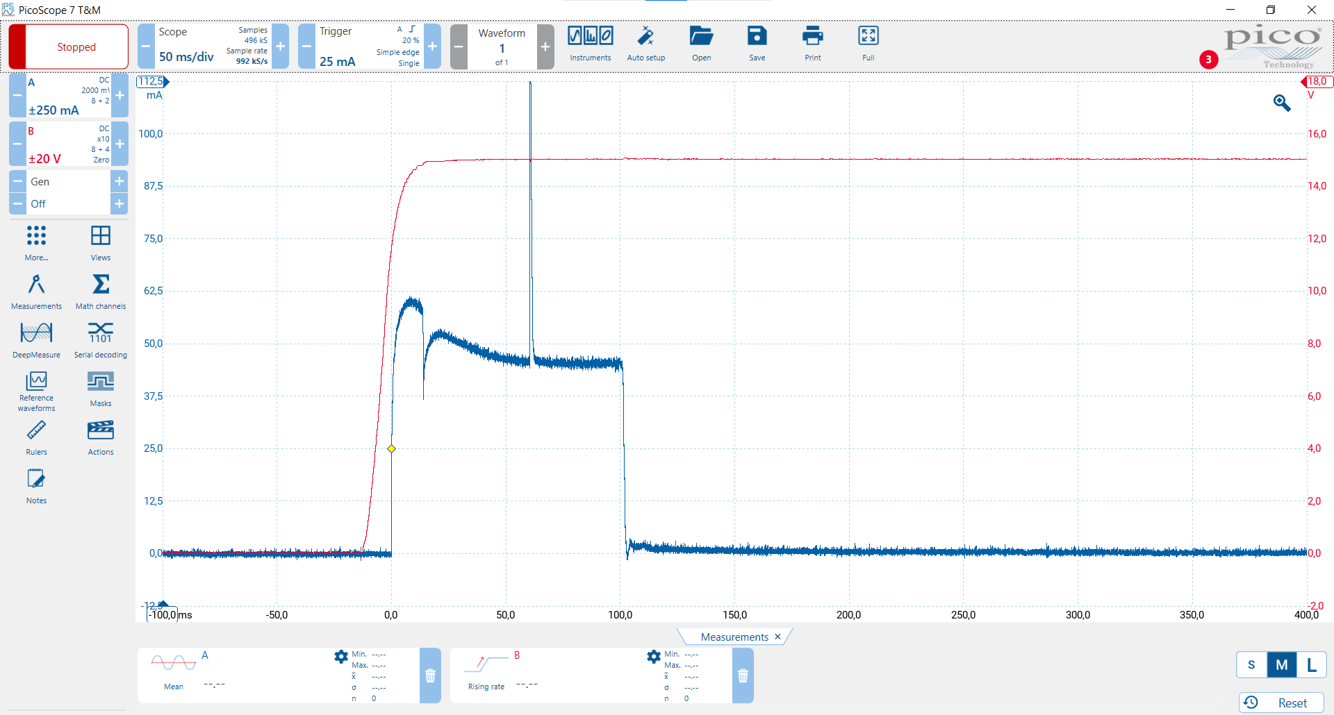
Vin is supplied by a DC/DC with a nominal output current of 333 mA and a current limit typically 170 % of that. As can be seen in the second image below, Vin reaches above 11 V before Vout even starts rising.
Load current and Vout:
Load current and Vin:
@Kerr.FAE
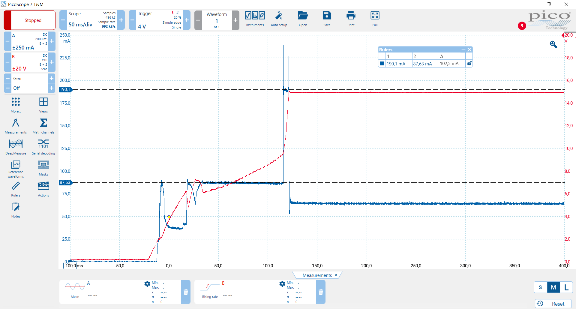
I already posted some images without Rlimit here.
Here’s another:
The current is limited to 87 mA during parts of the start-up. The same value I got with a resistive load of 82 ohms.
Hi @Kerr.FAE,
We have to make a decision on how to proceed and would like an explanation as soon as possible. Please don’t ask us to perform additional measurements until you’ve at least tried to reproduce the start-up current limit issue with resistive loads.
Hello @niklas.angare,
I heard back from some of our engineers and they let me know that the part may read the current as slightly higher than the true value during startup. The fix is to try lowering the value of Rlimit until the part is regulating at the 148mA that you are targeting.
They also let me know that the OC timer of 2ms is in fact blanked during startup. The 2ms timer only starts once the DVDT cap has been charged up. This means that the longer hiccupping time that you are seeing is set by the DVDT capacitance. You can try varying the capacitance to confirm this.
If you need immediate assistance you should submit a ticket below and someone in your local region will give you more direct support.
Best,
-Kerr
Hi @Kerr.FAE,
Thank you for this. What is the typical, minimum and maximum values for the current limit during start-up, taking this issue into account?
Speaking of which, what is the typical, minimum and maximum values for the current limit during normal operation with an Rlimit of 3.6k. It’s not clear to us from the datasheet which numbers apply, if any.
@niklas.angare ,
Since the typical current limits are between 25mA and 2A I would expect the values during startup to be just slightly less than that due to the current measurement discrepancy I mentioned previously. Unfortunately we do not have data for 3.6k Rlimit.
Best,
-Kerr