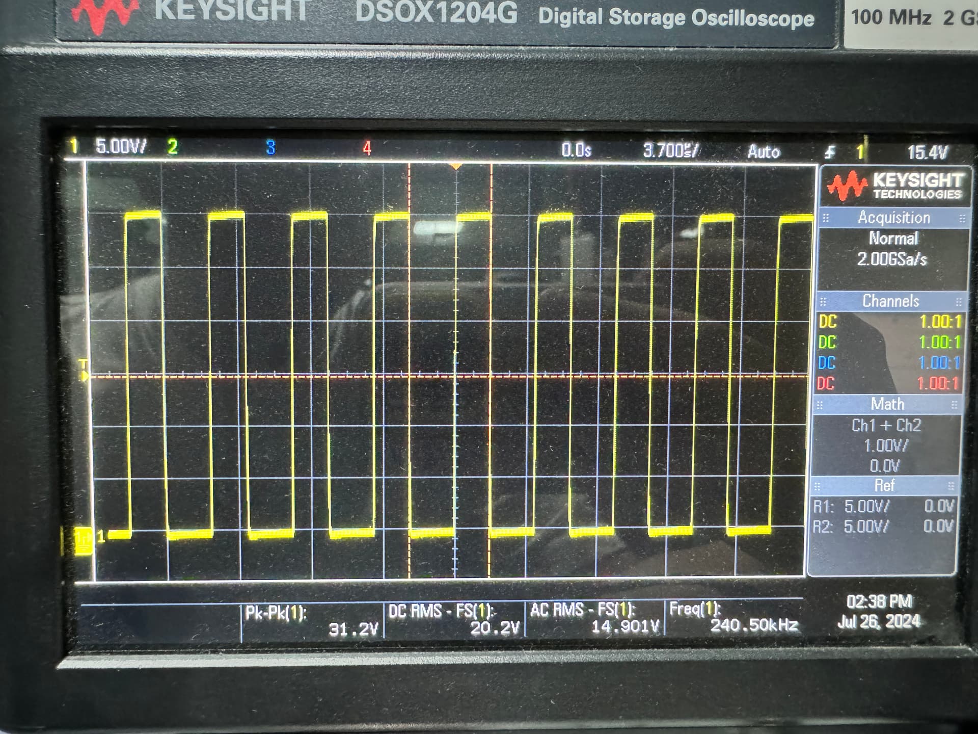
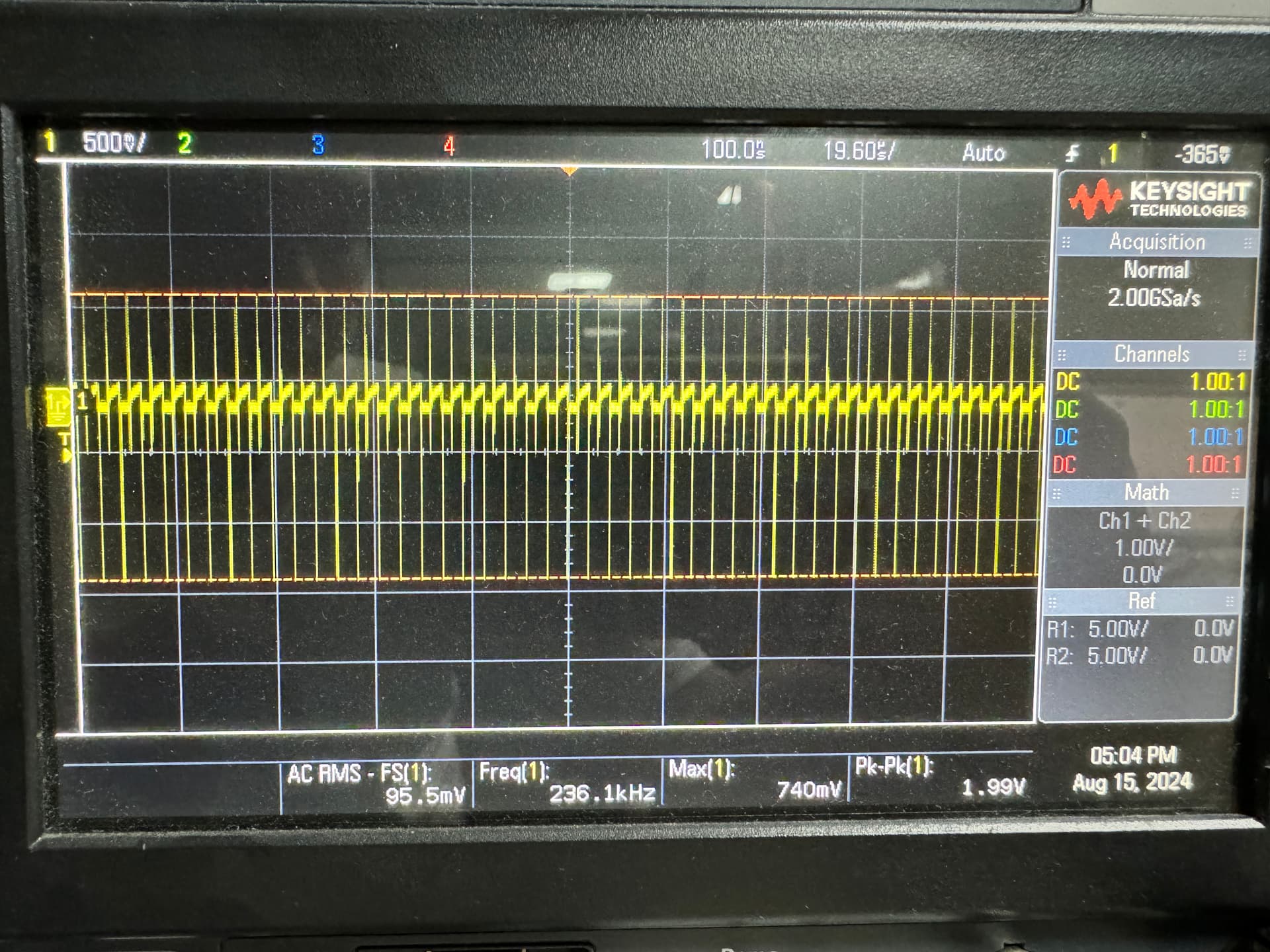
my project here required to build a dcdc for a audio amplifier rated at 200W, the required Vin is at least 30V. so I’ve been trying to setup MP3910 for a 12-24Vin, 30V 7-8A Vout boost configuration. But upon testing with the electronic load, it lost regulation just passed precisely at 1.96A @ Vin=13.8 and went into some kind of protection mode I guess, it keeps starts - stops repeatedly. SW graph is perfectly fine before failing, Nothing is overheated in this load. Maximum temp is just around 50C across the board.
Could it be a component problem? oversaturated current for the inductor?(I always feel sketchy about the inductor calculated results, it’s lower than this output config typically requried) etc.
the schematics are the same as datasheet provided - Figure 8: Typical Boost Converter Application Schematic-High Input Voltage Condition (with extra Vout and Vin capacitor used as well)
When I put your setup into the coilcraft DC DC optimizer. It suggests an inductor with an Isat of 25A
and calculates at full load (7A) that your peak inductor current is going to be about 20A.
So your inductor is undersized. Skipping all the complicated math, if your inductor was infinite, and your converter 100% efficient. The output power is 31.9V 7A 223W. So the input current at 12V would be 18.6A.
Does the output power go Up as Vin goes up? At a guess you can get 4A witth 24V in.
Also your current sense R is way to high needs tob e 0.8mohm to achieve your full power
I swapped with a big-ass 4.7UH inductor with 35A Isat and 6MOHM Resistor, It did better but still lost regulation after 5A mark. I am confused about your current sense R value as the formula listed in the datasheet could not able to calculate to that value, unless the peak inductor current is very high?
I got the peak current off the Coilcraft DC DC optimizer program. It is very nice as it points you to orderable parts and gives you loss and temperature rise for each of them.
The simplest possible calculation would be infinite inductance and 100% efficiency.
So starting there Vout is 31.9V and I out is 7A = 223.3W
Under the rosiest possible assumptions 223W at 12V is 18.6A
Now throw in 90% electrical efficiency your 18.6 becomes 20.7A
Now say the design point is 40% current ripple so +20% gives you 25.9A of peak current
Now go to your chip datasheet what is the minimum max current senes ( assuming you build more than 10 and want the all to work) I see 163mV
So 26A and 163mV gives a sense R of 6.2mohm ( oops must have goofed on previous calc!)
Have you hooked a scope to the CS input to the IC? Are you familiar with Kelvin sensing? It is easy through layout to pick up 1mohm of extra “sense R”.
You are almost there, I would start dropping the sense R or at least investigate what voltage you have at the current sense pin to gain insight. Also make sure your input voltage at load at the converter is still 12V if Vin drops that will give trouble too
dropping more than 6MOHM on CS will not help the output, seems like I need lower inductance per datasheet suggests. But if I use 1.5UH the efficiency will drop significantly (down to 89% @ 5A load comparing to 93% with 4.7UH), I guess I will have to try out different combinations to get the perfect juice.
Also, I changed inductance to 2.2UH with 5.3MOHM and it was able to pull 7.2A load @ 30V (with VIN = 13.8V and Iin = 17.12A, efficiency is around 90%). But, if I try to pull the max load instantly, it will 100% failed to regulate, I need to start from 6A and then lncrease to 7.2A, why?
So per the data sheet the maximum the control system will allow on the sense pin is 185mV. It looks like you are right there and any load past this point you will see Vout dropping. Your sense resistor needs to be lower, specially as you lower the inductance which will result in peakier currents.
This much power is non-trivial from such a low voltage.
Tested with a few combinations, 1.5UH with 5.3MOHM is the best I can get. Max 7.3A instant load without tripping. I tried lower it down a bit to 5MOHM but it will trip instantly, lower the switching frequency (only down to 200KHz) wouldn’t work either.
So you should be looking at the voltage at the Isense pin in detail. The max the IC will allow before it loses regulation is 185mV. There is also chip to chip variation so to be safe at full load you don’t want more than 165mV on that pin. In addition to the “nameplate” resistance of the resistor how you do the layout can add resistance to the measurement.
Not to bang away on this point, but at these currents layout is critical. So for example if your current path from the FET to ground is routed through a single small via, the netlist is fine, the connectivity is fine but you have a lot of extra resistance in that path. We also prefer 4 terminal resistors or a Kelvin connection, where the solder pad for the sense resistor is broken into a four pads big wide pads for the main current into the resistor and isolated ( current sense ) pads to read the voltage on the resistor terminals, not on the PCB somewhere near the resistor, and including all sorts of extra resistance.
I guess I’ll layout a new board to test it again. Regarding kelvin connection, I found an article here: LTC4218 12V/100A Hot Swap Design for Server Farms | Analog Devices , looks like this is the proper way of kelvin connection for multiple Rsense? (I’m using 3 Rsenses)
That is all excellent advice, the Fig 3 method I is better if you can get your layout people to do it. Did you double check that the sense pin is maxed out? The other thing that frequently bites are vias, if you need to use a via on the current carrying trace use big ones and lots of them.
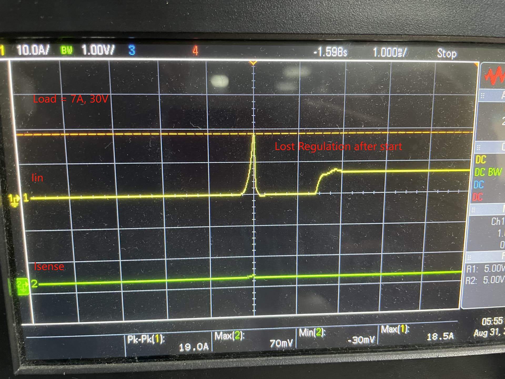
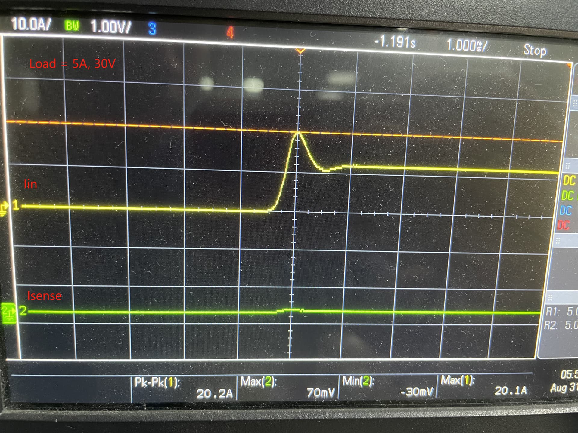
Good news: the new layout with dedicated kelvin connection works out almost perfectly, the load can be push up to 8A, 30V @ 19.31A, 13.8V without any problem.
Bad news: this only works if the electronic load starts @ 5A and increase all the way up to 8A.
so I use a current probe to check the input, there are a current spike around 20A when the load starts, but the current sense is well below 185mV, around 70mV at most. so… what else can trigger lost regulation?
I think what you are showing is the input current and the sense current. What is the Vout doing? This is a voltage regulator not a current regulator. I think personally that you are showing us scope captures of a system that is working perfectly now ( Congratulations BTW) and misinterpreting the results.
When you first turn the system Vout is way below the set point so the control system rapidly goes to maximum power. Vout rises, as soon as Vout is at the set point, now the control system has to rapidly go to operating power. In the case of zero load that would be zero current.
I think your system is OK now.
So I say go look at the output voltage.
Second item you can increase the SS cap ( try 10X more) and that will reduce the rate of increase of the current at the startup and may make those (what I think are perfectly fine) scope captures look more pretty.