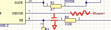
Use RC LPF to reduce th spike on the differential sense P&N.
Usually 100R + 10nF work very well.
For parallel cases you can either use two stage LPF or single LPF at the end of the sensing of the chip.
ENJOY~
Use RC LPF to reduce th spike on the differential sense P&N.
Usually 100R + 10nF work very well.
For parallel cases you can either use two stage LPF or single LPF at the end of the sensing of the chip.
ENJOY~
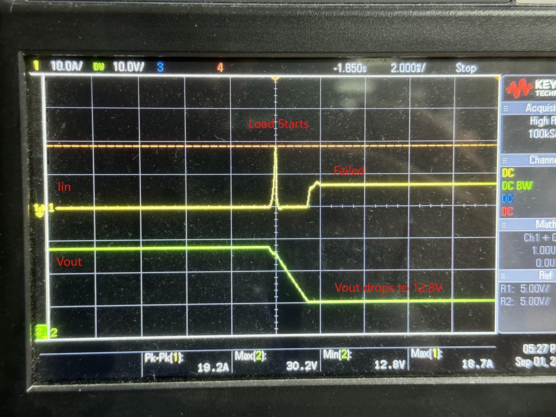
only the second pic here when the load is set @ 5A, 30V is working when the load starts pulling power. the first pic when the load is set @ 7A, 30V it will fail right after the load starts. Here’s the Vout:
Not really sure where do you want me to put it? You mean here?
Well that is weird. I would expect in an overload that the output voltage would smoosh down, this is the converter just turning off. Is Vin to the chip stable?
The RC network on the sense current is a nice trick and allows you to compensate for stray inductance of the sense resistor. The basic problem you have is that the voltage on the sense resistor is V= IR ( as we know) but also if there is some stray inductance + Ldi/dt
Enough inductance and the effect becomes significant and results in a situation where the resistor seems to be a higher value than it really is. Tuned correctly the RC time constant of the filter network to the sense R can compensate for the L/R time constant of the inductive resistor and give you a more accurate current sense signal.
Vin to the chip only has very slight dip upon the load starts and then come back to nominal. But never less than 12V. (Nominal 13.8V)
I also measured EN pin which is around 1.9V and it is very close to EN threshold, I thought that might be the problem but after changed to 332K + 100K combination (brings up to 2.6V away from the threshold) the probem still exists. VCC seems normal too.
If the current spike is fine as you see it then I guess it is not a major problem, at least on my end. I can deal with that later.
You had spike at the sensing during soft start state.
Of cause you put is at the current sensing nodes.
BTW are you sure this spike is a differential-mode noise?
Otherwise this cannot be settle via this method.
That was current spike at the Input upon start of the load. Not voltage noises
For reference:
when Vin is 24V or above (another designed operating conditions), no lost of regulation observed in 7A and 8A loads setup.
Maybe there is a quick spike on the Vin that disrupts the startup, put a cap on the EN pin.
Does it eventually work at 13V?
There are no voltage spike that I can see in Vin. Tried 1uF Cap on the EN, did not fix the issue.
The bulk capacitance of the input and the hot-loop is bad.
The parasitic L inductance of the copper introduce such spike if you are considering an input situation.
Place a gate resistor or bootstrap series resistor to reduce the spike.
The spike is both side btw informations are unidirectional when input got spike there must be a reaction paired on the output either a spike drop on voltage.
Action and reaction must be paired.
Bests,
Brian
The bulk capacitance of the input and the hot-loop is bad.
Are you suggesting I shouldn’t put too much Input capacitors in Vin?
Currently there’re 1 x 330uF + 4 x 10uF (not counting the 1uF for chip Vin)
Place a gate resistor or bootstrap series resistor to reduce the spike.
Already have one in place, as datasheet suggests.
First are you sure the source of the PSU do not have trouble on the transient of what you are experiencing?
If not then what happen when you reduce the bootstrap resistor and the gate resistor?
Do the spike get bigger? If so then this is clear to take what action.
If the above experiment is completed then I will suggest use 100nF to 47nF on the nearies VIN pin of the driver chip. 1uF is not good as the impedance on these MLCC is very high on high frequency.
@briansune
the PSU can pull much larger power than that.
And now my concern is not the spike. 5A 30V’s start up current spike is even larger than 7A 30V’s start up. But 7A 30V failed even before the spike reaches 5A 30V’s 20.8A spike.
What is going on at the SS pin? This chip has a hiccup mode overcurrent protection scheme. So if the OC limit is hit for a while will discharge the SS cap wait a bit and try again. I tried to make sense of the datasheet, but no joy. If you just want to try something make the sS cap 10X larger
@jshannon
oh, I forgot to mention, when SS cap was 0.22uF the behavior was like a shutdown I just showed you before and then repeatedly restart-shutdown in a fixed frequency, about 2 times/sec?
When SS cap is 2.2uF it would just shutdown like that and restart-shutdown takes longer period. The regulation will resumes normal after nearly 3-4 seconds if I shut off the load (0A).
and that is consistent with SS cap discharging / charging time.
So apparently this is still a OC situation? Then why it won’t trigger when the load is hot @5A and then increase to 7A? Doing so will not trigger the OC Limit.
Well I will just make up an answer, in the 5 going to 7 there is no or minimal overload, if you are trying to go from zero to 7 the overload lasts longer and the timer times out?
No what you are doing is very unprofessional.
There is always a slew rate on programmable load.
If you set the slew rate to lower setting from 0 to 7 and yet the issue still having trouble.
Then the story is very clear on all of us.
BTW the transient loading of a PSU doesn’t related to the maximum ability of the PSU.
PSU can handle a current transient with no issue on a range of current slew rate when once it jump above that specification you get into all kinds of trouble.
Do your PSU have voltage sense wire aka 4 wire configuration? If so use it to reduce the IR drop and transient trouble,
in the 5 going to 7 there is no or minimal overload
That is correct.
go from zero to 7 the overload lasts longer and the timer times out?
also correct, with 2.2uF SS Cap.
@briansune
Interesting insight,
I’ll mess around the PSU and the Load then get back to you.
But no the PSU don’t have voltage sense, it’s not the expensive model having those fancy IOs.