Hello, this is a similar inquiry to this thread and this thread. The datasheet formulas are rather difficult to follow with the units being unclear, as well as lacking any example calculations.
I am trying to make a calculator for the MP3363, and am finding odd results with the inductor calculation “Equation (4)” on datasheet page 11 (image below). 257nH and 474nH both seem strange.
Can you tell me what is wrong with this cell formula?
Alternatively, since the datasheet does not provide any example calculation to understand the units, it would bee helpful if you could provide an example calculation using the formula.
The spreadsheet mentioned above is available in Excel format here
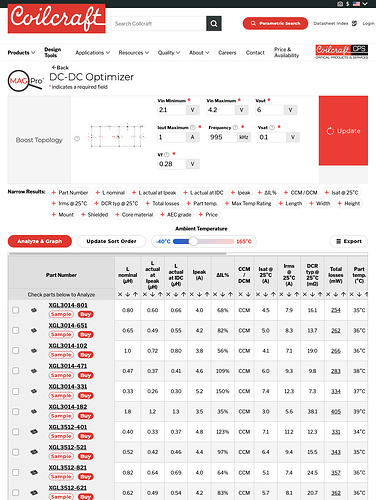
The money sentence is “the inductor should operate in CCM mode”. Personally I am doubtful that this is required but taking it at face value I would ignore their spreadsheet entirely and get over to Coilcraft dot coms DC DC designer page. Select a boost converter and put in the minium LED current and the maximum input voltage into their calculator with say 50% current ripple allowed (CCM mode) then it will spit out a giant list of parts that work, their sizes, their losses in the application, their temperature rises etc. It is magic
Interesting, I was not aware of the Coilcraft DC-DC optimizer. The top-sorted results are in the ballpark of my spreadsheet calculations, around or above 0.257-0.474uH. Strangely small values to me, but the datasheet does say that equation 4 is for minimum values.
The MP3363 datasheet doesn’t seem to state the characteristics of the internal NMOS, so kept Coilcraft’s default ‘switching transistor’ voltage drop of 0.1V. The 0.28Vf is assuming a Toshiba CUHS20S30 diode.
Thank you for this tip, this is a very useful tool.
Glad you like it, I have no affiliation with them other than an admiration for their website.

