I’m designing a single-cell-powered device. By looking at application example (EV2626-R-00A) I expect that battery-backed part of my system should be connected to PMID pin (SYS node). This expectation is partially inspired by this topic. Now that I have my PCBs assembled, I’m not so sure anymore. There are no power on PMID, when 3.8V is supplied to BATT node (from PSU).
Or, maybe, load should not be connected to PMID? Unfortunately, I cannot find any clues about where the system load should be connected - to PMID pins, to battery cell directly, to VIN (not optimal for my case), elsewhere?
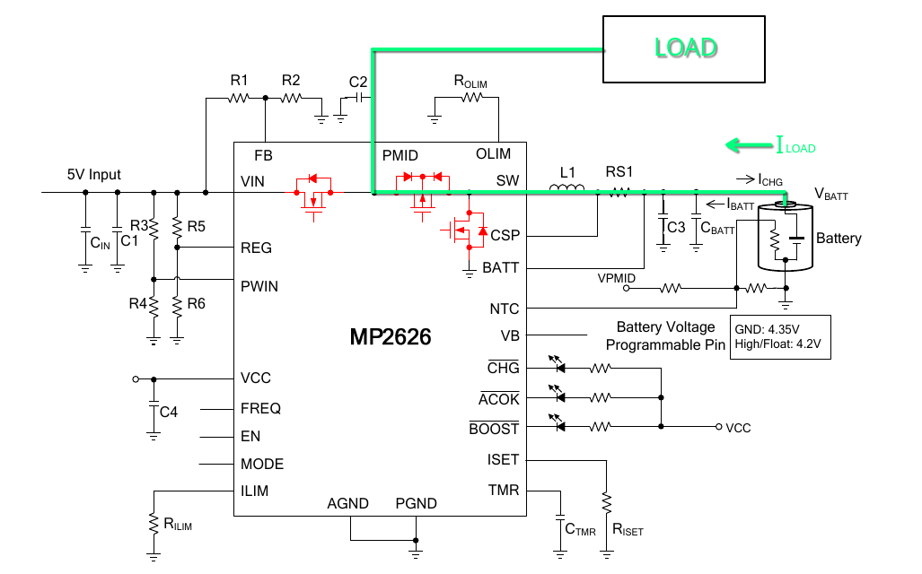
Relevant part of my schematic is exact replica of EV2626-R-00A.
Pin states as follows:
EN is grounded - no charging is required at this point
MODE is grounded - no boost operation needed as for now
VB is high - 4.2 LiPo is used
VCC is not loaded as per documentation (used only for tying MP2626’s logic pins high)
10K NTC is connected as recommended
Did I get system load current path from battery correct? (when no VIN is supplied). If yes, what else to check?
I see that you have your PCB made and are running into issues with this part meeting your desired application. I can answer your latest questions below:
You are correct, you may only discharge the battery in BOOST mode.
While it would be possible to connect VBATT directly to your load and isolates VIN, it would require additional external components (external switches may manually connect the battery to load and isolate Vin, but the timing would need to be carefully designed to avoid damaging the IC by ensuring the input and output don’t become connected in parallel). And while such a system would theoretically work, it is not in the typical application of the MP2626.
My goal is to design a portable and battery-efficient system, which occasionally could act as USB host. The problem is, it does not require 5V, except for rare cases, so MP2626 seemed like an ideal solution…
So, if I reconnect my load directly to battery, it will still be possible to utilize MP2626 for charging and boost. Except for that, MP2626 would be in sleep mode (leaving Vin isolated), right?
Assuming that you have the external components like the external switches that are timed correctly (or something that serves a similar function successfully in implementation) then it would still be possible for charging and boost when you reconnect your load directly to your battery while also isolating your input.
By doing this, you would be bypassing SYS regulation, so it would be good to make sure that physically isolating the VIN circuit doesn’t conflict with the logic of the power management of your IC.
If you are not too late in your design cycle, it may even be for the best to choose a different power management IC if having a direct VBATT connection that would be better suited for your application. The following parts also have low dropout (to ensure minimal losses when directly powering the load from the battery) and various integrated protections: