Greetings. I encountered a problem that the MP2617B does not fully charge the battery. Charging turns off and 4V remains on the battery. The battery does not charge up to 4.2V.
I tried several options for setting the System Voltage parameter with resistors.
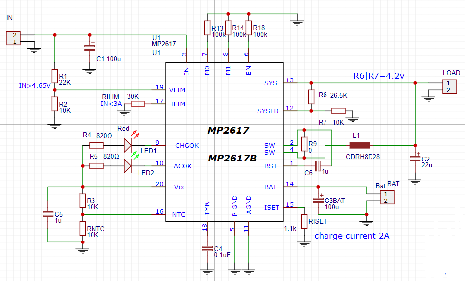
- R6=26.5k, R7=10k for voltage 4.2V - The battery was charged to 4V. No more.
- R6=33k, R7=12k for voltage 4.3V - The battery was charged to 4V. No more.
- Option without resistors. pin SISFB floating (not connected anywhere) - The battery was charged to 4V. No more/
While the charging process is in progress, there is 4.1V on the battery, and 4.3V at the output of the SIS. But as soon as charging is turned off, the battery remains at 4.05V. This is not correct. After turning off charging, the battery should be fully charged and have a voltage of 4.2V. But alas, this does not happen.
In addition, the battery does not receive a current greater than 530mA. I measure the battery current through a 0.1 Ohm shunt (R100).
I take the charging voltage from an adapter for charging a mobile phone with an output voltage of 5V. The charging current does not exceed 430mA.
Why can’t I charge the battery to 4.2V?
I am attaching a diagram with the part values in the attachment.
I have tried several different 18650 batteries for charging. They all charge up to 4V. At the same time, if I charge the same batteries from the TC4057 microcircuit, they are fully charged to 4.2V.
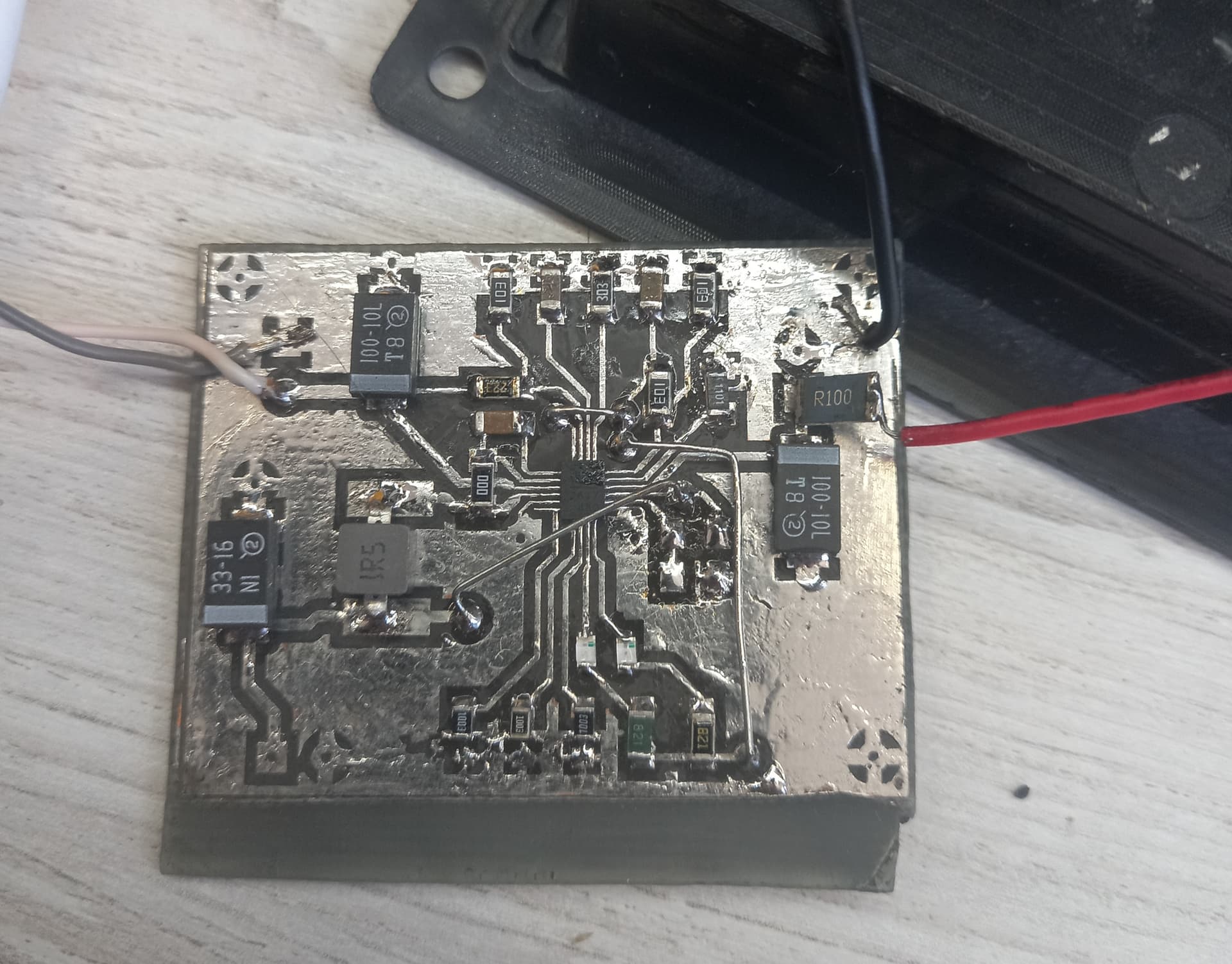
This is what my breadboard looks like:
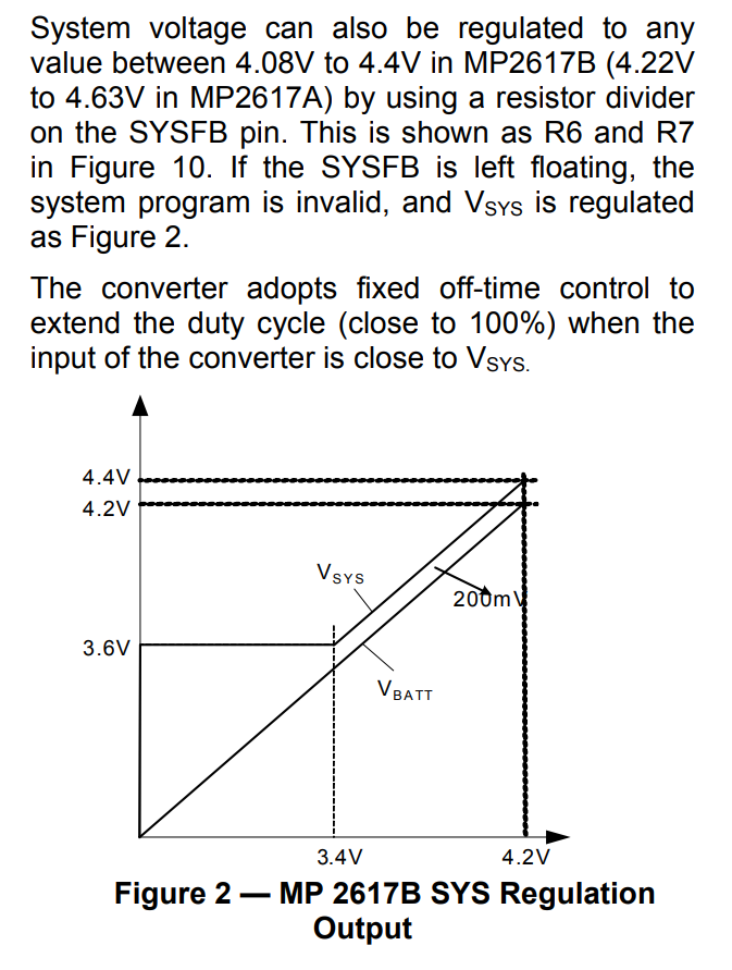
Complicated chip that is working as intended. Figure 2 of the “B” data sheet shows that the Sys voltage is 200mV above the battery voltage. So a 4.2V sys voltage means a 4V max battery voltage just what you observed. Raise the Sys voltage to 4.4V and watch your troubles disappear.
1 Like
Thanks for the answer. Yes, I paid attention to this point from the faq. I tried to achieve this, but apparently I ran into inaccurate resistor ratings. I will try to change the values of the resistors once again
Hello @JoyJoTix,
I reviewed your schematic and it looks fine as per USB 2.0 Mode configuration. I agree with @jshannon with the idea of ramping up the Vsys to 4.4 V and this will lead to Vbatt as 4.2 V.
It is also important to choose the feedback resistors at SYSFB pin with recommended tolerance ratings. For this case, it is 1%.
Please let me know if you have any questions.
Best,
Saquib
2 Likes
Thank you for your answer and attention to my question. I changed the resistor values. R6=40kOhm, R7=15kOhm. According to formula 7 on page 26 from the datasheet it turns out (Vsys_ref=1.152V):
Vsys=1.152x((43+15)/15)=4.45V.
I’m trying to charge the battery again. Again, when the charging is turned off, I observe 4V when measuring the battery voltage. During charging, the voltage Vsys is 4.35V and on the battery itself is 4.09V.
Perhaps it’s worth calculating resistors for voltage VSIS 5V? To ensure that we take into account the inaccuracy of resistor values and the inaccuracy of Vsysref voltage for my MP2617 copy? According to the datasheet, Vsysref may be 1,135 - 1,170V.
At the moment I continue to charge different batteries. Now one of the LEDs has gone out. But I haven’t turned off the input voltage yet. The voltage at the VSIS output is 4.2V. At the same time, the battery is 4V. How can this be? I installed R6 and R7 for a different voltage.
Vsis tracks 200mV about Vbattery. The battery should continue to charge and its voltage will rise, and the Vsis voltage will rise as well. I suspect the chip is working perfectly, just not as you expect.
Refer again to figure 2 Vsys is 3.6V minimum or Vbatt+200mV
How big is your battery relative to your charge rate? The last little bit of charge can take a while
LED going off is charge termination condition being met fully charged, or almost fully charged
Well the issue is how accurate is the 200mV number? The datasheet implies that it might be between 100mV and 400mV. So it looks like on your particular chip it is 4.35-4.09 or 256mV
I’m not denying that the chip works well, but it’s not correct. A battery with a voltage of 4.2 V is considered charged. And is there any alternative to mp2617, because what I see now does not suit me.
I have just conducted an experiment. I took a pre-charged battery up to 4.1 V. On the board with MP2617, I soldered R6/R7 to adjust the Vsys to 4.7 V. I installed the battery, turned it on and charging stopped immediately. Then I installed R6/R7 so that the Vsys was 4.4V. I installed the battery, turned it on and charging stopped again.
So a precharged battery of 4.1V is over the charge initiation threshold. Take a battery of 3.6V and run it.
The bottom line is that 4.1V battery is not a full charge. If I use a cheap linear TS4056, then it will continue charging up to 4.2V. I must admit, I did not expect such problems with the mp2617. Maybe I’m doing something wrong, but I’m disappointed.
You aren’t doing anything wrong, the chip isn’t doing anything wrong that I can see. It is a mismatch in expectations. A linear will cause a lot more heat.
I suggest trying it first with a 3.3V ( depleted Li-ion ) and see what happens.
I expect the battery will charge nicely to 4.2V and then stop
I tried to charge the battery, which was discharged to 3V. The battery capacity was 4000mAh. I even rewired the input current limit to 1A. Okay Charging has started. When the LED went out, but with a cable connected to the adapter, the output voltage of the MP2617 was 4.28V, and the battery was 4.09 V. After I unscrew the cable from the adapter on the mp2617 charger, I get 4.07V and on the battery itself, too, 4.07 V. At the same time, I rewired the tuning resistors so that I had 4.5V output. Yes, I know that the MP2617 supports up to 4.4V output. As a result, anyway, I can’t charge the battery above 4.07V. For portable devices, losing 0.1V due to undercharging of the battery is a very significant problem. Are there any chips similar to MP2617?
So it looks like it worked again, the battery charged up to 180mV under vsys which is within tolerance of the specified 200mV. What was Vsys set to in this case? I believe there is a default option that if you don’t set Vsys it defaults something. sensible
Currently, the Vsys is configured, according to calculations, to 4.47 V. I even tried to leave the Vsys floating, but the dr 4.2V battery does not charge.
it looks like the Sys floating is they way the intend it to operate. I would try with a discharged battery with the Sys fb floating and see what it does. I am a huge fan of eval boards, they answer so many questions for a mere 50 bucks or so.
I found another interesting MP2637 chip on the site. I’ll study it and order a couple for experiments. The MP2617, for all its elegance, delivers a lot of worries.