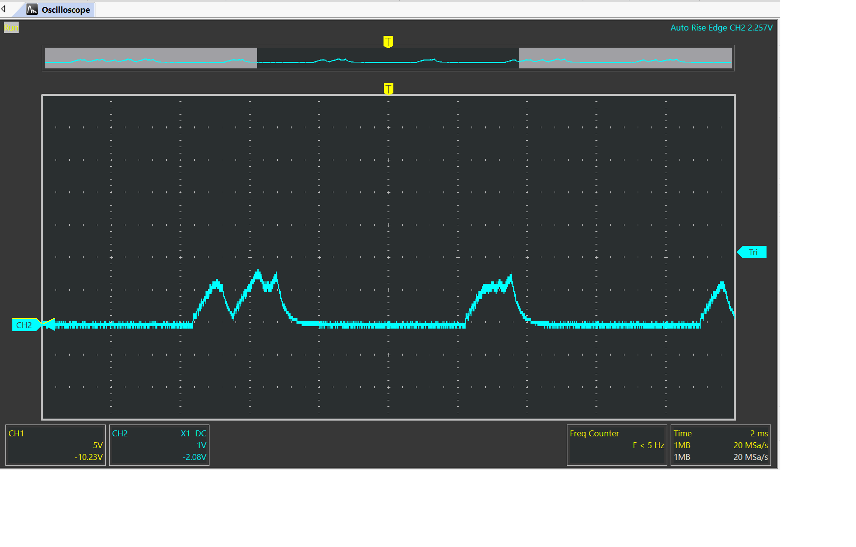
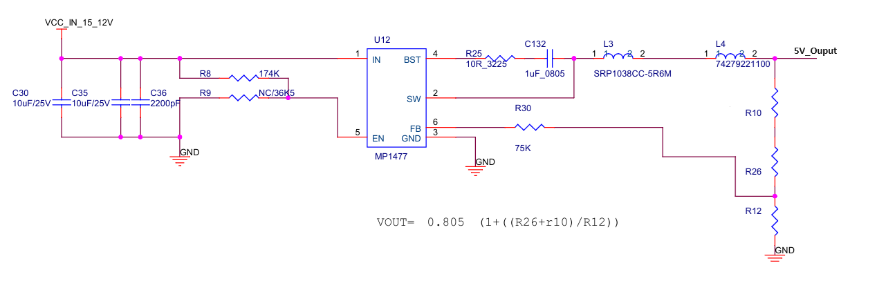
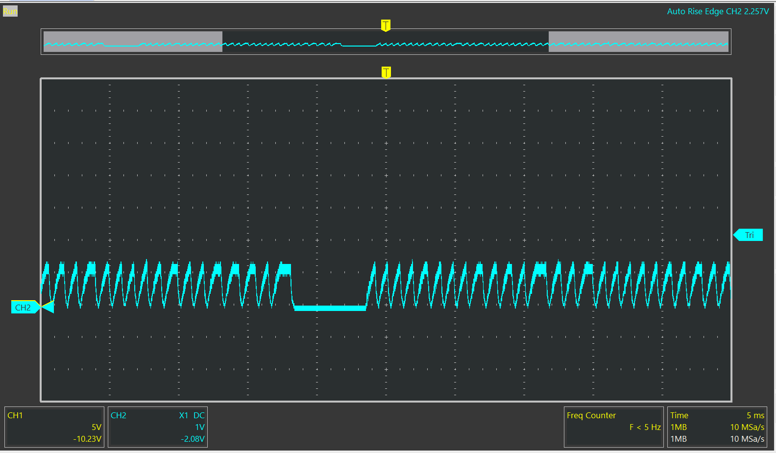
I have configured a input 12V to 5V output Volt circuit using mp1477. Then, I performed a load test, and the output was 5.23V at no load, and it worked normally at 1A (5.18V), but at 2A (toggleing Voltage), the output voltage had an abnormal waveform.
Vin?? Inductor value, and its saturation current? How do you know the load was only 2A?
Vin ==>12V
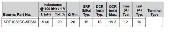
inductor ==5.6uH
Register
Loader
inductor saturation…
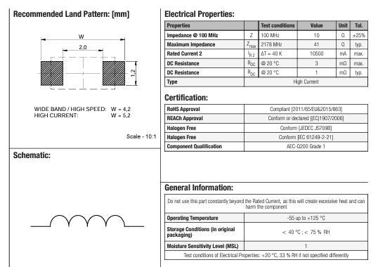
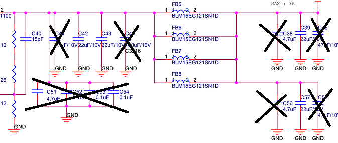
L4 ==> Ferrite Bead
I don’t see any output capacitance. It is important
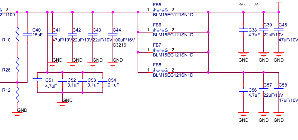
That is rather a lot of output C. I wonder if you are invoking some overcurrent/hiccup mode. The data sheet shows only 44uF you are at 250uF. Can you unsolder a bunch and see what happens just for fun?
I agree… consider Inductor to ‘ferrite’ ratio 10:1, cap ratio 1:2 to 1:10. i.e.
6.8uH inductor → 680nH second inductor. 47uF First capacitor <470uF second capacitors.
see: Ridley Engineering | - [052] Designing a Two-Stage Output Filter for Low Output Impedance
A good article, worth getting familiar with. Note, the feedback should come after the second inductor. The ferrite bead shouldn’t be in the inductor/output capacitor current loop.
Simon
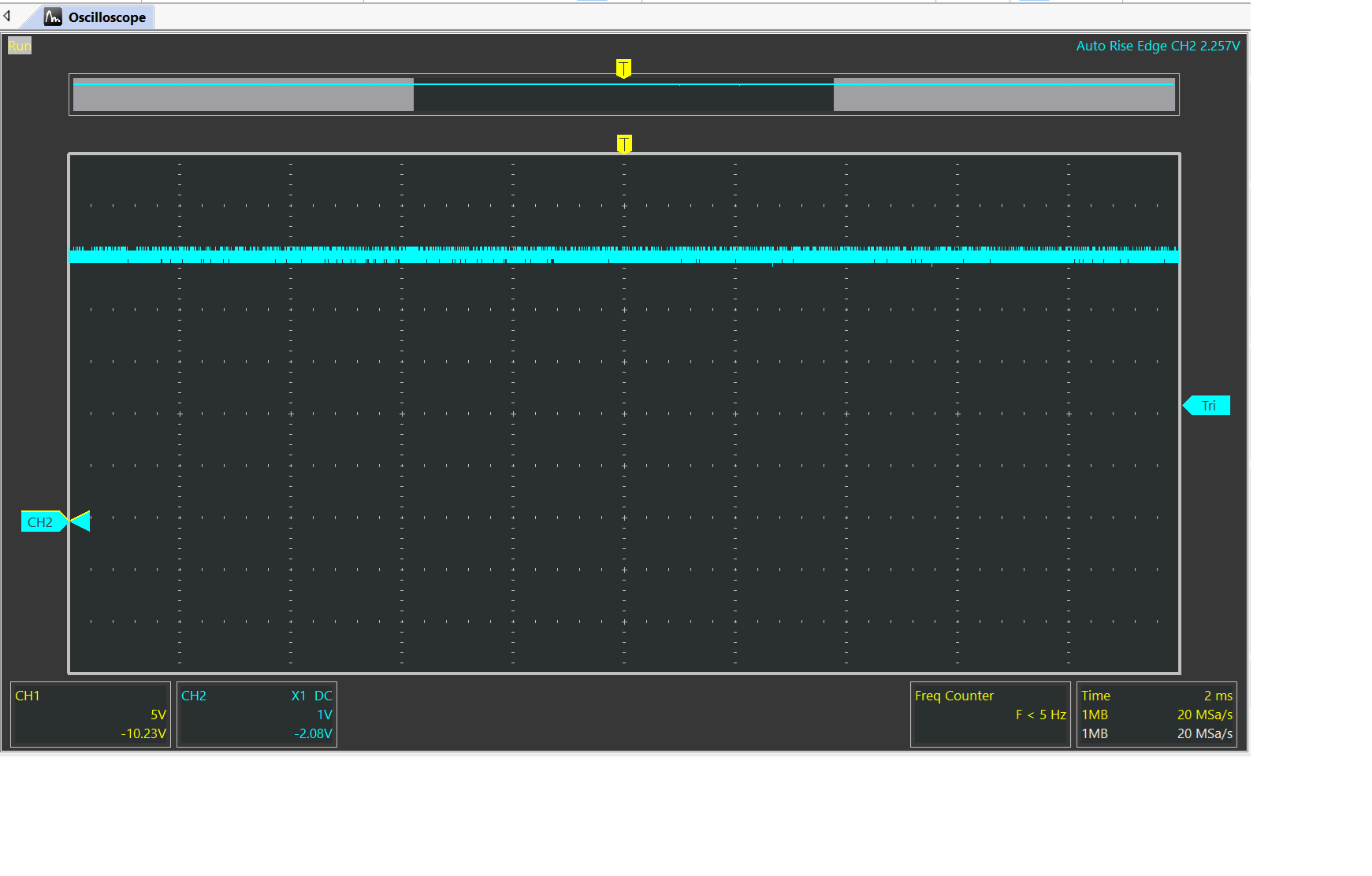
I tried it like the picture capture, but there was no change at all.
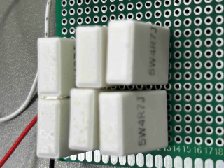
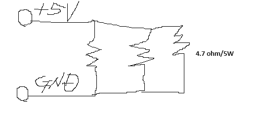
Oh this is embarrassing, your load is 3 4.7 ohms in parallel? That works out to 1.56 ohms. 5V on 1.56 ohms would be 3.2A! So you are overloading it and seeing the correct functioning of the overcurrent protection perhaps. Get rid of one of those resistors
There are 3 parallel resistors, each 4.7 ohms. (3x 4.7 ohm)
So that is an overload. Try 2 and see what happens. It looks to me also like this really isn’t a 3A part. The datasheet valley current limit can be as low as 2.7A . If I was naming this part I would call it a 2.5A part. Perhaps I missed something
I removed one resistor, now it consists of two resistors, and it doesn’t work. It only works when there is one resistor. From what you said, it seems that mp1477 is 1.5A(max), not 3A(max). How do you perform load tests?
Unlike the waveform that oscillates when there are three resistors, there are many oscillations when there are two resistors.
Well I use a Kikusui electronic load, but resistors are fine. It looks like with 2 resistors it is on the verge of working. by my reckoning it should work load is 2.4A with 2 resistors. Is any other circuit connected to this? Also have you checked to be sure Vin is a stable 12V? To be honest I am running out of ideas
No other circuits are connected. There are only two resistors connected in parallel. This happened while I was using a lot of other DC-DCs and was changing from the TI model to the more cost-effective MPS model, so I think it will be difficult to consider the MPS model in design anymore. The mp1477 specs types 3A (Max), so I tried the mp1477 because it seemed competitive in terms of unit cost, but in reality, it doesn’t seem to work at 3A (Max), so I’m going to stop development. Thank you very much for your help this time.