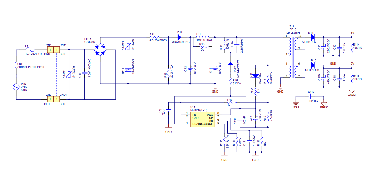
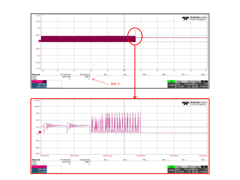
The circuit design was tested by plugging it into the same outlet as a blender. It was observed that when the Pulse button on the blender was pressed, the voltage at the drain pin of the MP024-10 IC reached 849V, which caused the IC to fail.
The points I would like to know are as follows:
- The circuit board design was not in use; it was merely plugged into the same outlet as a 1000W blender. Does the interference come from the blender, and what type of interference is it?
- Where in the circuit design is incorrect?
- What could be the causes of the voltage exceeding 700V?
Additional information:
- Testing with an ELCB also showed overvoltage exceeding 700V, but it occurred less frequently compared to the test with the blender.
- The circuit diagram can be found in the attached images.
Based on the circuit design, is there a solution or approach to fix this issue?
The voltage waveform exceeding 700V at the drain pin of the MP024-10 IC.
So you have some crazy amount of distortion and noise on the incoming AC line? Created by a blender and this has induced a malfunction during turn off. Does the physical proximity of the blender matter or is it simply a case that it has to be on the same plug. What is happening to the output voltage during this malfunction.
I would say you are testing this application circuit more rigorously than anybody else. Is the blender a cheap stand in for a more defined line side IEC test.
1.It is simply a case of being plugged into the same outlet.
2. The blender’s power cord complies with the 60227 IEC standard.
3. We previously tested a circuit using the IC MP020-5 in the same way, but no overvoltage was observed at the drain pin.