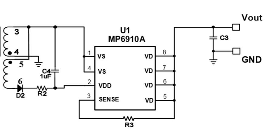
I am using MP6910A,but the voltage between VD and VSS is high ,almost 0.8V, why?And the voltage between VDD and VSS is stable 15V. My circuit is typical circuit. It seems doesn’t work. 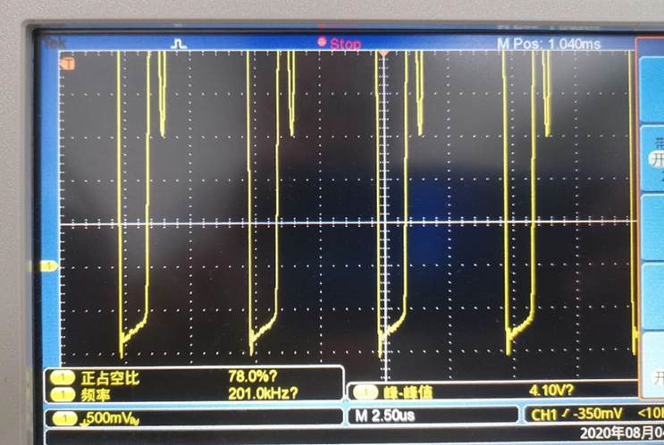
Hi Wesley: Can you please provide your Output voltage and Minimum and Maximum Load current. Also please share the load current under which this waveform was taken.
Please refer to page 9 of the datasheet. The light-load enter pulse width (tLL) is fixed internally (~2.2μs). When the synchronous power switch conducting period is lower than tLL for longer than light-load enter delay (tLL -Delay), MP6910A enters light-load mode and latches off the integrated MOSFET. This is the reason for the drop being almost 0.8V. The internal body diode of the Mosfet is conducting. Also it is likely that the Primary magnetizing inductance is too low. Can you please share the details of the transformer inductance, total max output power and the load current range ( min and max) and also the load current at which you captured the waveform?
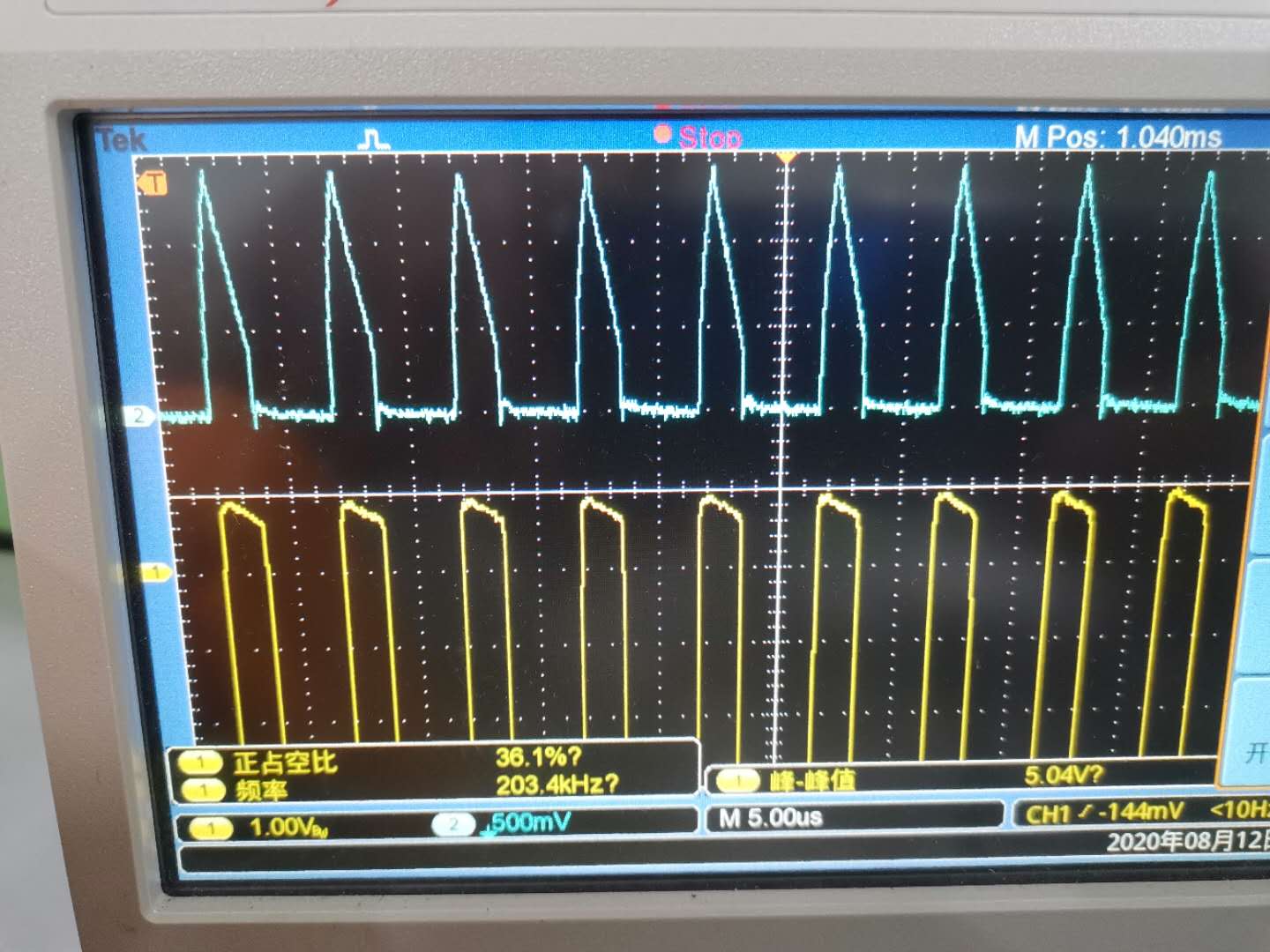
blue is current.1V=10A. yellow is VD to VSS.
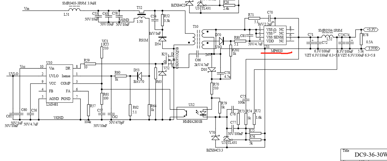
From the waveforms, it seems the load is at 3.8A when you took the scope shot. Also it looks like the full load current is 9A based on the fact that this is a 3.3V, 30W power supply as per the title of the schematic. Also since the pulse width of the sync rectifier is 2usces which is between the tLL specs of 1.4usecs to 3.6usecs you have entered the light load mode and that is the reason the mosfet is off and the body diode is ON. Also the power loss in the part in this condition is already 3W. This is probably making the part very hot. The temperature rise must be around 90 deg C. This part is not correct for 9A of current at 200Khz switching frequency. The MP6910A is recommended for 2.5A of output current. Your load current is exceeding that.