Hi,
I used MPM3683-7 to generate 0.85V from 5V but it doesn’t work at all.
I designed the following schematic that seems to have no critical problem in my view.
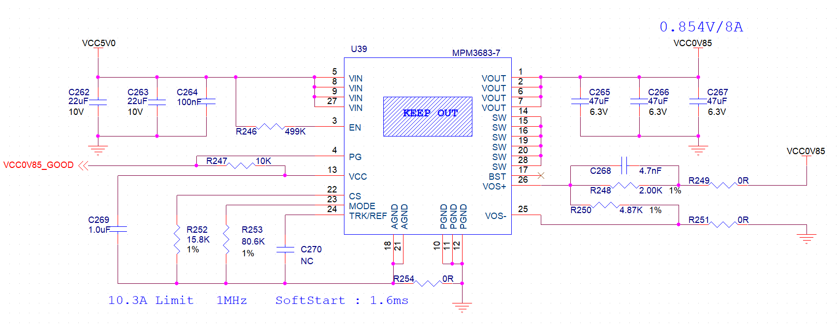
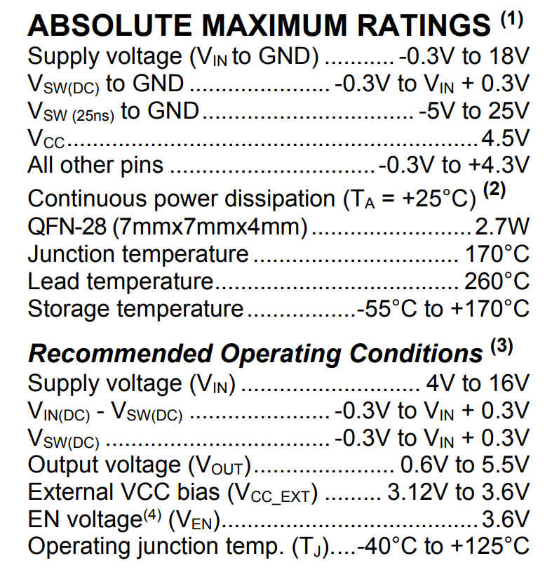
When 5V supply(measured as 4.99V) is applied to VIN, EN signal is measured as 4.75V(which I’m not sure it is clamped by the Zener diode in the chip) but VOUT doesn’t rise. Voltages on TRK/REF pin, VCC pin and SW pin doesn’t change at all and are stuck at 0V. TRK/REF and VCC pin are not short to ground. Temperature on the chip doesn’t seem to change at all.
Even when I detached load from VOUT, the problem doesn’t disappear.
I want to know the following things.
-
Does my schematic have issues that make the chip not work?
I connected all SW pins all together like the evaluation board(EVM3683-7-QN-01A) schematic but the layout of the evaluation board doesn’t seem that those pins are connected. Is that a problem ? -
Any other thing to check further
I have no idea which to check.
On PCB, I found no copper in keep-out area under the chip.
Is any special caution required on SMT reflow?