Hello everyone,
I am working with the MP2672 battery charger IC to charge a 2-cell Li-ion battery in balance mode using I2C communication with an ESP32. However, I am facing an issue where charging does not start. The battery voltage is being read as VBATT, and VSYS also reading same amount of voltage, but the IC is not supplying 8.4V for charging.
Setup Details:
- MP2672 used in I2C mode with ESP32.
- VBATT is set to 8.4V, but the IC is reading the battery voltage instead of initiating charging.
- Charging is not happening.
- I2C communication is working, and I have successfully read the register values.
REG00 (0x00) = 0b0111000
REG01 (0x01) = 0b10001111
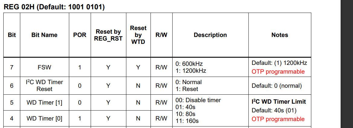
REG02 (0x02) = 0b10010101
REG03 (0x03) = 0b00101000
REG04 (0x04) = 0b10000000 // Watchdog Timer Expired
REG05 (0x05) = 0b00000000
Also, how do I stop watchdog timer from expiring, every time i read the register’s values.
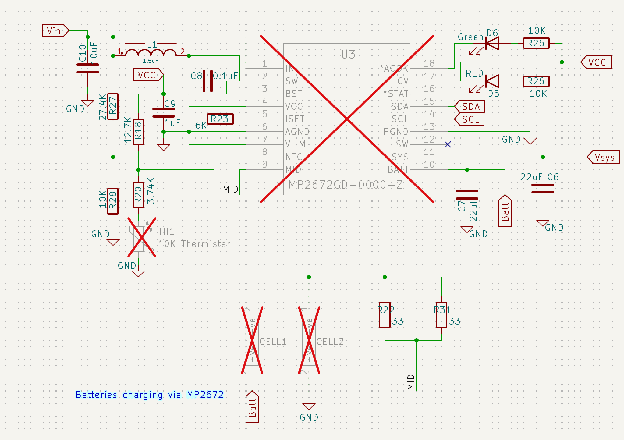
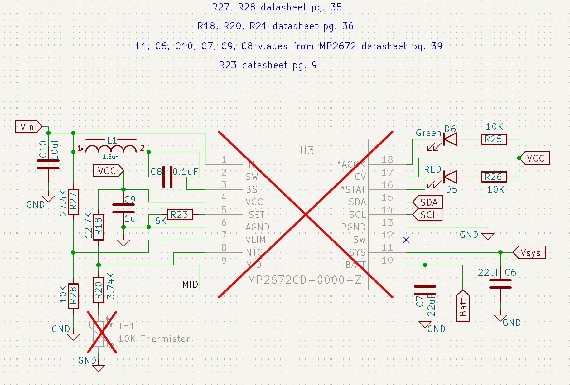
This is the schematics i have designed:
Hello itsmeayushzile,
You are saying Vbatt and Vsys are being read as the same voltage. Are you measuring these and what is the voltage?
You can disable the watchdog timer with the reg 02h.
I measured the following voltages:
- VBATT = 6.91V
- VSYS = 6.88V
- Both battery cells = 3.46V each
Additionally, REG02H is an OTP (One-Time Programmable) register. Can it be configured via I2C using ESP32, or is it only programmable through the MPS GUI with the EVKT-MP2672 evaluation kit?
You should be able to use i2c to configure the register.
Per your values Reg03 states that this is in cc or cv charging.
Also, what is going on at the stat pin? is the led on or off?
The STAT pin LED is ON, indicating charging; but VBATT and VSYS are reading the same voltage. Also, the watchdog timer has expired. I tried configuring the registers via I2C using ESP32 but was unable to write values. Any suggestions on how to successfully configure the registers via I2C?
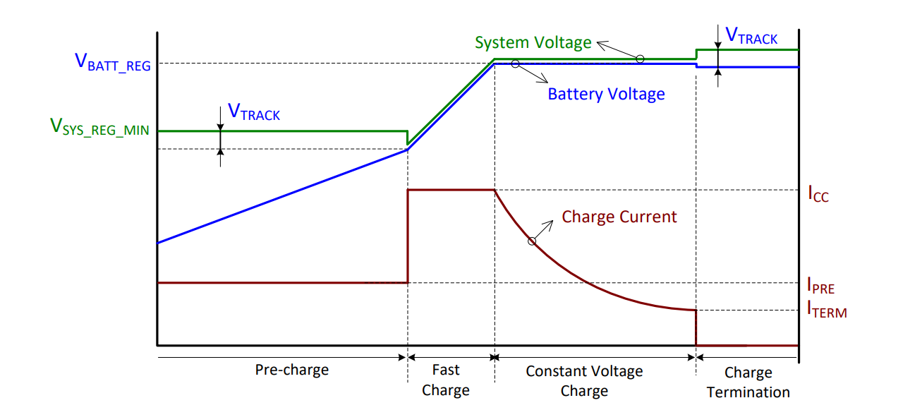
The image below shows the charging states. Having a system voltage near the battery voltage occurs for both fast charging and constant voltage charging. Fast charging is initiated after Vbattpre is reached and lasts until Vbattreg is reached. You should be fast charging at these voltages. Aside from the voltage being the same how were you determining that charging was not occurring?
Sorry for the late reply.
As per the graph, VSYS should be higher than VBATT during Fast Charging and Constant Voltage Charging, but in my case, VSYS is lower, behaving as if it’s directly powered by VBATT. Despite understanding both charging modes, after half an hour of charging, the cells and IC heat up to 80-85°C, with minimal discharging.
Still looking for a solution. Any insights would be appreciated. I can provide more details if needed. Thanks!
To help further assess please provide a screenshot of your layout.
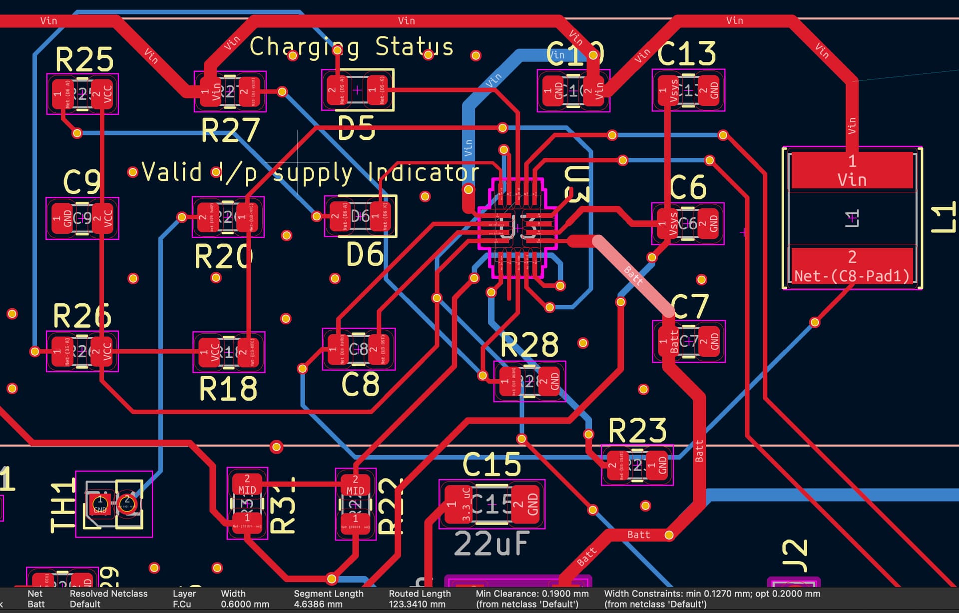
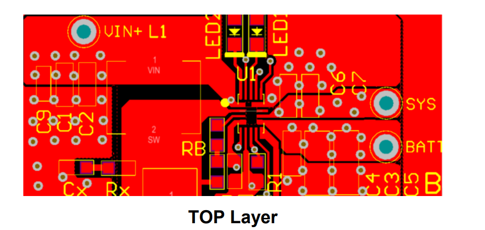
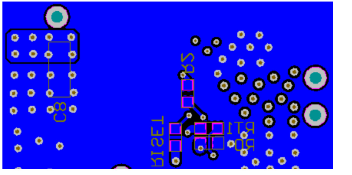
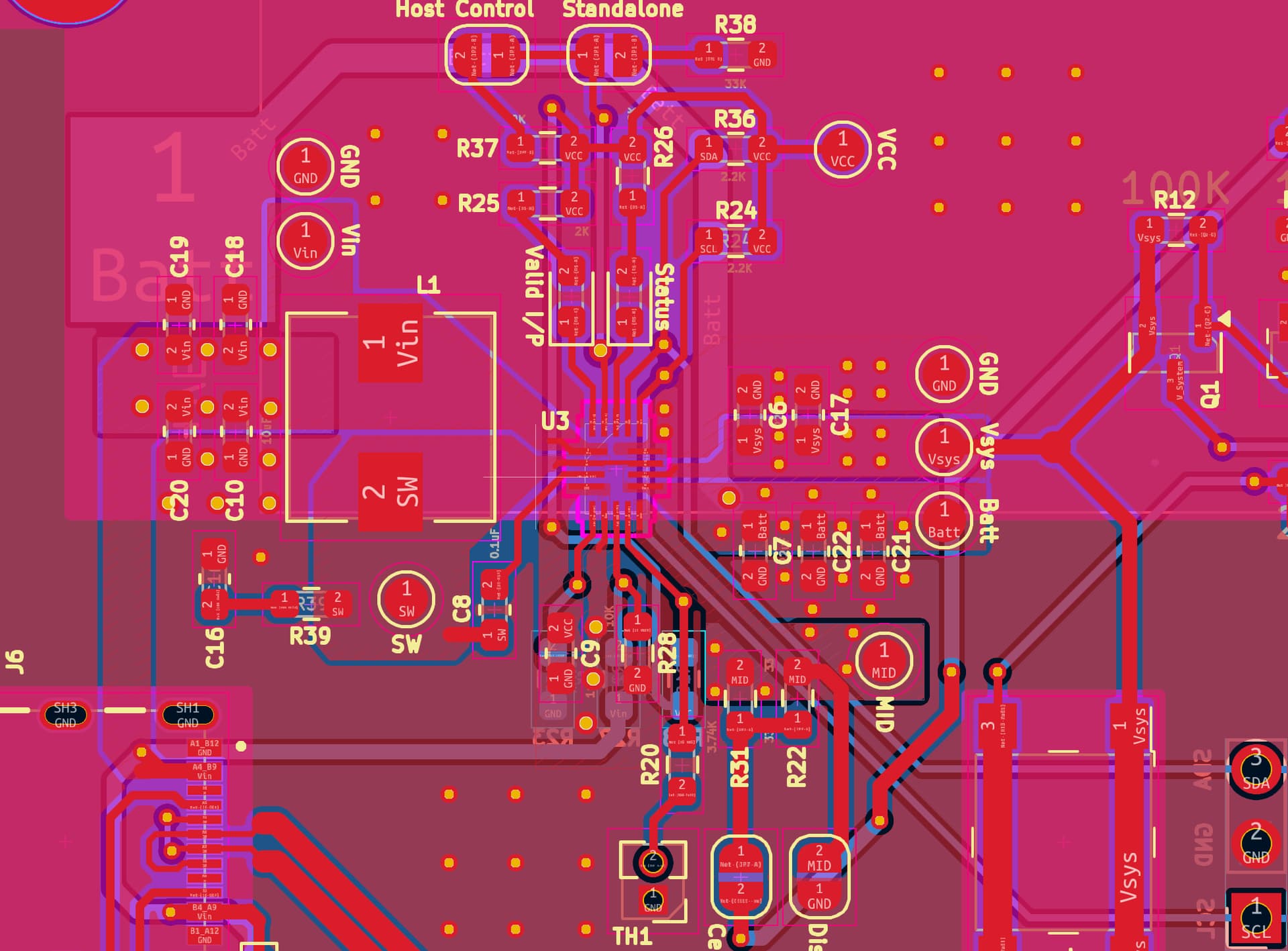
This is the layout i have designed
Hello itsmeayushzile,
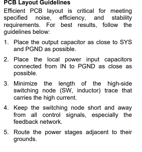
I believe that you should modify your layout to resemble the screenshots below more closely. You are trying to charge your battery at 2A. The input path seems to very long and you are routing it through multiple vias and thin traces. The traces that handle power should be larger copper areas. I think you could also optimize the component placement and reduce the lengths of paths.
Here are some additional instructions from the datasheet.
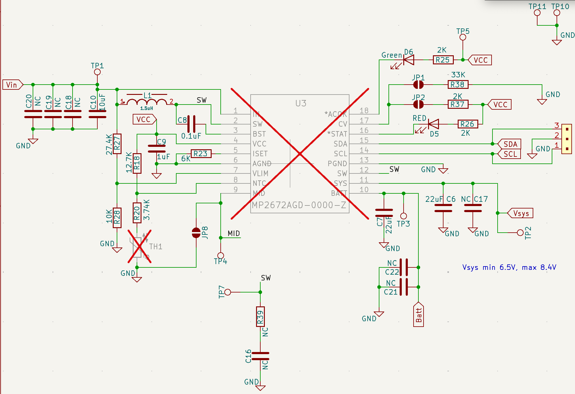
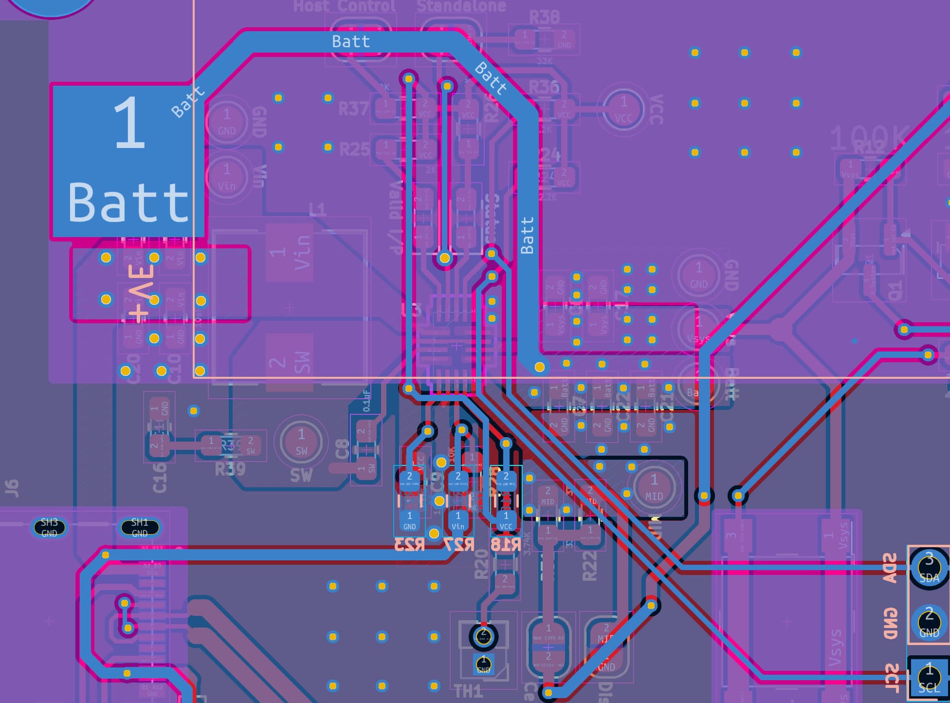
i have modified my layout and designed according to pcb guidelines, adjusted trace width, can someone review if its appropriate or if anything is still missing?
I think you have achieved a better layout then your first and more closely followed what our example shows. Wider traces where needed for power and shorter paths where specified.
Notes: Your input capacitors although both connected to ground at similar distances to SYS I am not sure how putting them on different pads will affect behavior. Our board also did not have large Vbatt path on the back.
1 Like
Thank you for your feedback and the Vbatt path (wide enough to carry 2A current) goes to one of the cell’s +ve terminal.