Hi everyone,
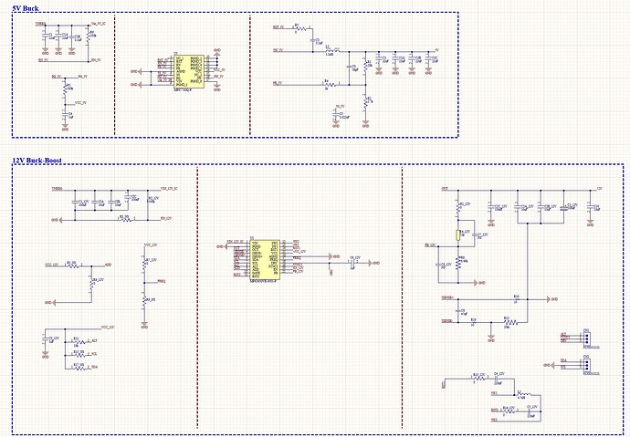
I’m working on a power supply project and would appreciate your help reviewing my schematic. I’ve designed a circuit using two main ICs:
- MPS4245 - Configured as a buck-boost converter to generate a 12V regulated output. It uses an unregulated input ranging from 10V to 16V, which is typical for a battery. This IC will also be configured and monitored via the I²C programming interface.
- MPS8771 - Configured as a buck converter to produce a stable 5V output from the same unregulated 10V to 16V input.
Here are some key details about the design:
- Input Power: Unregulated 10V to 16V battery source.
- Output Power Requirements:
- 12V output (via MPS4245).
- 5V output (via MPS8771).
- Control Interface for MPS4245: I²C communication for programming and monitoring.
Concerns:
- Schematic Accuracy: I’d like to ensure that my connections, component selections, and general layout for both the MPS4245 and MPS8771 are correct. Are there any glaring mistakes or missing components, especially regarding stability, filtering, or protection?
- I²C Programming for MPS4245: I’m new to programming power management ICs via I²C. Could someone guide me on how to set this up, what tools or software I might need, and how to program the registers for my required settings?
- General Design Check: Any tips on how to optimize or validate this design would be greatly appreciated.
I’ve attached the schematic for reference. Your feedback on improving the design or addressing potential pitfalls would be extremely helpful!
Thanks in advance for your help!
Hello,
Thank you for your question, I have provided my responses below.
-
The 12V buck-boost you seem to have mostly followed the EVB. In terms of the sda and scl portions, when actually implementing the design appropriately size pullup resistors for i2c communication. For the buck you seem to have followed the recommended the typical application for 5V output.
-
we have an evb and gui available which allows for an easy way to interface with the part.
-
MP8771 is available for DC-DC designer and MPSmart. The MP4245 is also available for use on virtual bench pro.
1 Like
Hi Eduardo,
Thank you for your helpful response—I really appreciate the insights!
For the pull-up resistors on the SDA and SCL lines, would a value around 10k ohms be suitable for a 12V Supply? My assumption is that pulling them to a stable power supply would be ideal, rather than the converter’s 12V output (since it will need to be programmed initially). Does this approach sound correct to you?
Thanks again for your assistance, and I look forward to your advice!
Best regards,
-Gio Hernandez
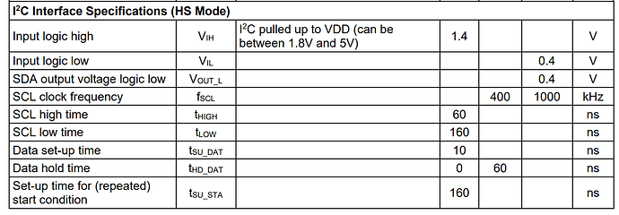
The pull up resistor are sized based on speed of communication protocol. In this case it seems that the typical protocol used is at a speed of 400kHz, shown in SCL clock frequency. There are general recommendations based on speed that you can research online but you just want to make sure the timing requirements are satisfied. If you are running into timing issues decreasing the size of the resistor will help due to decreasing the R*C time constant.
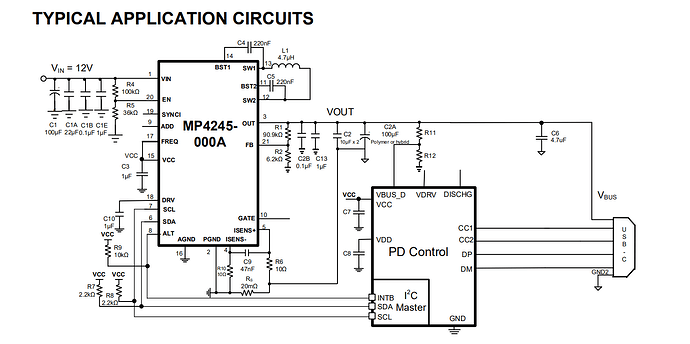
The datasheet shows 2.2k for this example shown in the screensheet. You need to pull it up to appropriate voltages based on logic levels you need to satisfy and that are not above the 5.5V maximum for pins. The datasheet shows being pulled up to Vcc which is what you are also pulling it up to in your circuit node labeled VCC_12V. Do not pull it up to the power output of your converter.
2 Likes


