Hi,
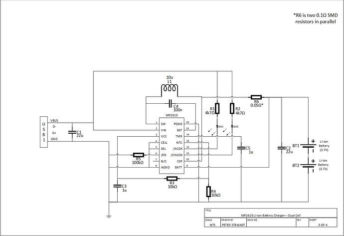
I am just prototyping two similar designs using the MP2615C. The first design is for charging a single cell from a 5V supply. This works well. The second design is for charging two cells. But for some reason this does not work.
The voltage input for the Dual Cell Charger is around 10 Volts. When I connected two Li-Ion Batteries which are charged to 7.2 Volts, I get around 15 Volts on the input supply. No current is drawn. However, on the SW pin (1) I see an oscillation signal of around 3 MHz. I am not sure what I have done wrong on the second design. Can you advise?
Hello,
Welcome to MPS forums. The resistors on the pins CHGOK and ACOK might limit the open-drain sink current below the minimum value i.e 5 mA which would affect the charging functionality of the part. I would recommend replacing it by 1k ohm and check battery charging.
It is always recommended to minimize the SW and current sense resistor trace lengths as well as prevent the SW network from interfering with the feedback network in order to avoid noise on the SW node.
Please let me know if this helps.
Best,
Saquib
Thanks for the reply. I thought the 5 mA minimum on the CHGOK and ACOK inputs was to indicate not to use LEDs that require more than 5 mA. Note, on my design for the single cell 5V input version I have used resistors that allow the same amount of current to flow as for my two cell version. The single cell version works fine. Also, I have used the same components and breadboard layout for the single cell version . The only differences are the LED resistors (1.5k) and the inductor, 4.7 uH on the single cell version. I will, however, try reducing the LED resistor values and let you know what happens.
That is cool, the converter is running backwards and boosting the input voltage from the battery.
Do you have an EVAL board these can be helpful
I did try reducing the LED resistor values. It made no differences to the operations, as suspected. The only effect was to make the LEDs very bright. I also tried changing the CELL pin input from being grounded to being open circuit. This also made little difference with only a reduction on the voltage fed back to the input power supply. I am suspecting the breakout PCB I designed for the MP2615C LQA chip may not be making good solder connections with the chip. I am going to try mount another chip onto another breakout PCB. Although this is proving to be difficult. There is no real way to tell if the connections between the PCB and the LQA chip are good. I have used a microscope to examine the solder joints, but I am still not sure.
No I do not have an Eval Board. I designed and had manufactured a Breakout PCB which converts the MP2615C LQA package to a 16 Pin DIL. The rest is prototyped onto stripboard. I’ve also discovered that my single cell version is not quite working correctly. I calculated, using a current sense resistor of 0.05 ohms, that the maximum charging current should be approximately one Amp. The current rarely goes above 200 mAmp, which, when charging a 3300 mAhr battery, takes a long time. I have even tried grounding the TMR input, disabling timeouts, but this also makes no difference. I will try and make another PCB breakout. If that does not make a difference, I think I will give up and try a different chip - one in a SOIC or similar package which is easier to tell if all the pins have been soldered correctly.
Stripboard? I don’t know what that is but it sounds very forgive me ( home hobbiest) Switching power supplies feature large currents fast switching edges and sensitive analog circuits reacting to millivolts. Very impressive it works even at all. You will save yourself time and money with an eval board.
You are most probably right about the Eval Board. I have used stripboard (aka Veroboard) on many of my prototype designs with reasonable success. However, all my switching power supply designs usually operate as less than 100 kHz. I believe the MP2615C operates at around 760 kHz. This may give me some problems and be very layout sensitive. I think I will look at a different approach.
