Hello,
Is it possible to use or configure the HR1001B LLC controller to run in an unregulated SMPS?
We don’t want to use the regulation loop, and we need to be able to set the running frequency.
And if that scenario is possible, will the HR1001B run as an LLC topology?
Thanks
Hello Paul,
While this isn’t outlined in the typical application of the HR1001B, this should be theoretically possible.
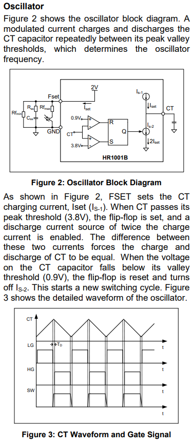
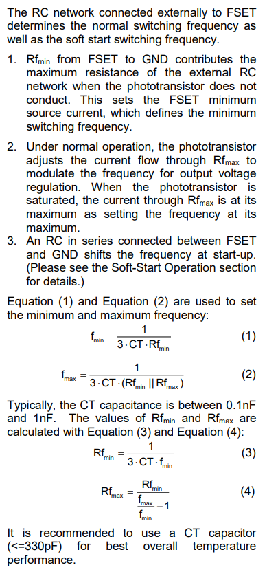
If you are going to try this, you’ll need to ensure that the controller uses a fixed switching frequency. This would need to be near the resonant frequency of tank components. The unconnected feedback loop would either be unconnected or tried to some voltage instructing the controller to run at a constant frequency.
So for setting the switching frequency on the HR1001B, you would just need to ensure that the min and max switching frequencies are set close together alongside selecting the passives that get your switching frequency close to your tank resonant frequency.
Please read into the following section from page 13 of the HR1001B datasheet for more context on this:
Also, since it has been some time since your initial question, please let us know if there have been any updates.
Best,
Krishan
Krishan,
Thank you for your answer.
We still need to test the circuit and see if it works.
Can you help us suggest the values for the HR1001 circuit because we are new to LLC?
For example, for a 64VDC SMPS fed from a PFC.
Thank you
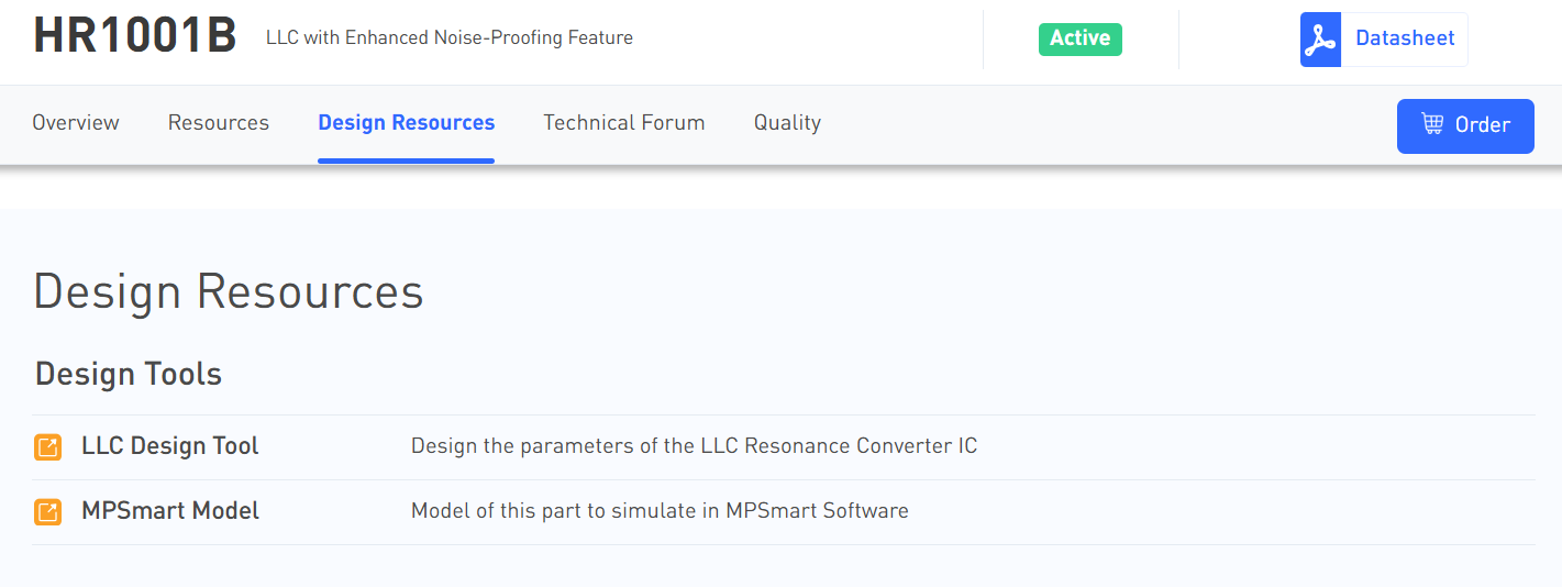
We do have simulation software like MPSmart that supports models of the HR1001B that you can refer to in terms of populating a full schematic. There is also our LLC designer tool which may be of some assistance as well.
This is on the following HR1001B MPS Website page under the Design Resources tab:
I am interested in learning more about your system. Since your Input is from a 65Vdc SMPS, what is your total output power? Vout? Are multiple outputs needed? Do you have an efficiency target?
I want to understand if the HR1001B is truly the best IC choice for your application. I assume you will need the isolation, and if the power level isn’t above 240W, maybe a Flyback would suffice here.
Best,
Krishan
Sorry, input from PFC 400VDC and output is ±64VDC center tapped.
Thank you for sharing the tools
Our typical DC input application for this typical design has Lm = 870µH, Vin = 450Vdc, and fmax = 140kHz, so Vin = 400Vdc should be fine.
Getting the secondary side of the device to have components that can be configured to handle your output voltage relative to what works in the MPSmart software is your best guide in this case. Let us know if there are any other questions.
Best,
Krishan