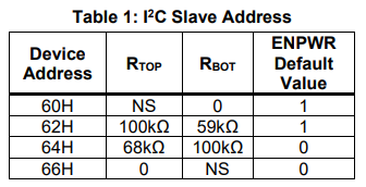
I’m trying to figure out whether the advertised USB PD for this device is at all achievable. For this, an output voltage range of 5V to 36V should be achievable. As of now, we are testing with the evaluation board, which by default would not be able to supply for this range, given that Vref is programmable from 300mV to 2.047V, and the voltage divider allows for a maximum voltage of about 20V on the EVQ4214-U-00A. To address this issue, the voltage divider resistor R2 was exchanged from 10kOhms to 5.1kOhms, which allows for a 38.2 V maximum voltage if my math is not wrong.
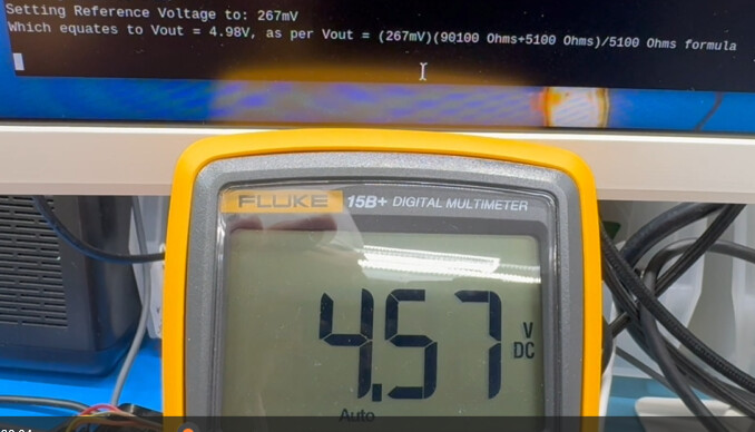
But on doing so, the IC looses the precision it used to have on the past voltage divider resistor configuration. And I’m wondering whether it’s my math that’s wrong or if it’s just that I’m pushing the IC well over its operational limits. Steady state error seems to be around ~0.5V now that we’ve changed R2 value (that’s if my math is right), added to this the IC caps at 33.5V rather than the expected 38.5V. I do believe the issue should be one of the following:
- My math’s wrong
- Should I change the Compensation components now that I’ve changed R2 value? If the answer is yes, how should I determine what the new values of the compensation components should be?
- The IC is designed to operate on 36V output, but the evaluation kit is not, could you confirm this?
For a reference, I based my calculation off of this PDF file
PDF with my math