I need to design the power supply of an smart meter powered via three phases (L1/L2/L3/N) so a lot of input voltage is going to be handled.
I will list some important requirements:
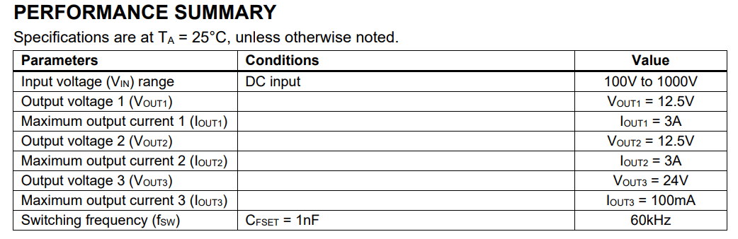
Output voltage: 12V
Fully isolated.
-
Device needs to keep working when a single phase has power*
The power supply preferably has its switching frequency outside the CENA (35 to 91 kHz) and FCC (150 to 480 kHz) bands to not disturb Power Line Communications (PLC) sensitivity. If switching frequency is below 480 kHz, special attention needs to be paid to filtering harmonics.
-
PLC receive levels can be lower than 40dBuV*
-
The input impedance of the device (PLC coupling and PSU) must be at least 50 Ohm in the CENA and FCC band. (e.g., by using PLC rejection filter on PSU) EN50065-7 (Signaling on low-voltage electrical installations in the frequency range 3 kHz to 148,5 kHz. Part7: Equipment impedance):*
-
10 Ohm from 3 to 9 kHz*
-
50 Ohm from 9 to 95 kHz (Rx),*
-
5 Ohm from 95 to 148.5 kHz)*
-
EN50065-7 does not cover FCC band. PSU shall reach > 50 Ohm also in FCC band*
Input Voltage Range
100 - 265 VAC | AC3 (-20%/+15%)
Input Voltage Tolerance
0 - 437 VAC | ACx (+90% to -100%) for 1h
Input frequency: 50-60Hz with ferquency crange: class F2 (±1%)
This also must meet, apart from EN 55032 EMI:
According to EN 60255-27:
2kVrms (60sec)
±5kVp (impulse)
According to EN 62368-1:
6-8kVp (1…4sec)
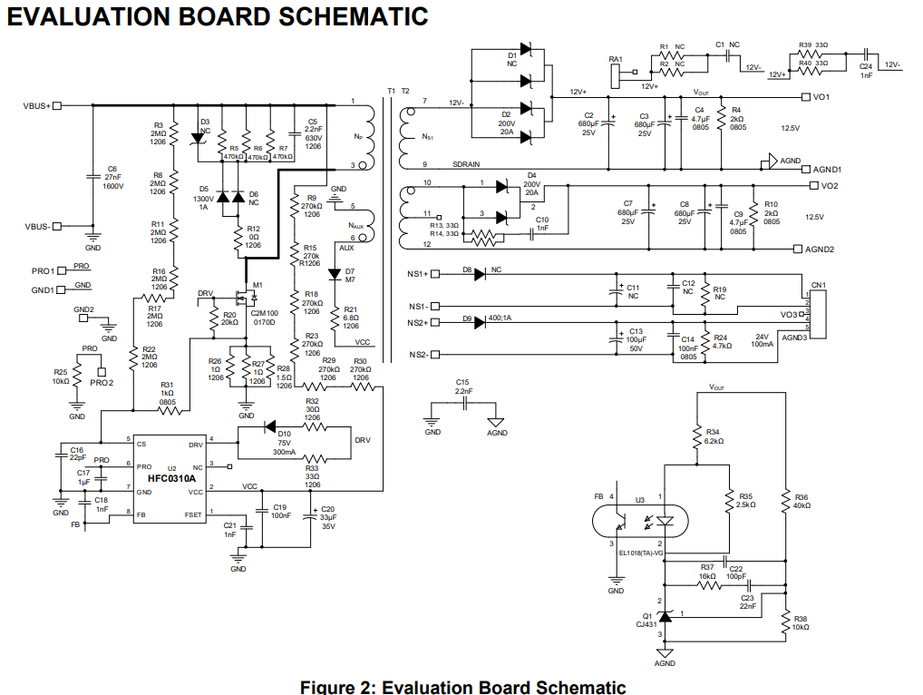
From my point of view, the most straigh forward solution is using a flyback using the HFC0310A as it has a Configurable Switching Frequency (fsw) up to 600kHz and therefore avoiding the PLC bands. This states to stand up to 1000V but there is not a lot of documentation about this.
On the other hand, there is the e StackFET technique for using lower voltage controllers as the HFG611-45 which it might also be targeted for larger powers.
Could you provide me any help on the topic? maybe I am missing something.
The HFC0310A is a good IC that I also think would be a straightforward use case for the application given the switching frequency capability of 600kHz.
For the 1000V input rating for this IC, are you referring to the following design example from the datasheet? There is more documentation of this on the EVB that aligns with the design example:
But of course, these ratings are only attributed to the application of this design. Defer to the maximum recommended ratings of the actual IC in the datasheet, but this should be a good reference schematic for these ratings from the EVB datasheet and potentially for your design.
Here is another IC with extra documentation that would perhaps be of some interest:
This IC may be overkill for a 10W design, but it does take EMI and THD into consideration with the design example when presented in the datasheet. This is assuming you were flexible on other topologies besides a flyback. I have seen the HR1211 be used in various power supply applications is all.
Let me know.
Best,
Krishan
Hello Krishan,
Thank you for your reply. Yes, for the 1000V i was meaning that design example. However, as you can see that example has a fsw=60kHz. I am not sure how good it would behave at 550kHz or sim… Do you know if something similar could be done at this frequency? Is there any transistor that can handle this?
Is MPS planning to release a flyback controller for this specific application taking into consideration the FCC band? or maybe customer have to deal with what MPS already has.
On the other hand, yes I am fully open to other topologies. I was not evaluating them because of the power range but they maybe could fit the specs due to soft-switching. Have you ever seen an LLC with these voltage and power levels? could MPS help on the design?.
Hello,
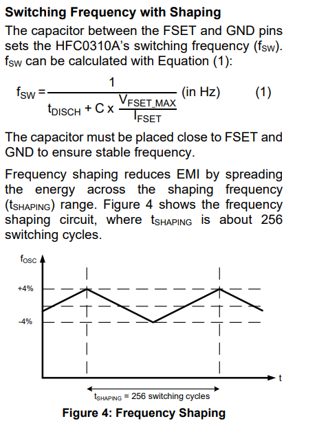
Yes, the switching frequency in this case would be changed based on the capacitor between FSET and GND using the following equation (page 15 of the HFC0310A datasheet:
I suppose in this regard, you would be taking into account of the FCC band you were speaking about. Be sure to check the datasheet for other components in the datasheet that would need to be sized based on a different switching frequency as well. I am not sure about an exact transistor that you could use, but feel free to size this relative to your own target application.
Hope this helped. Let me know if there is anything else you wanted to follow up on.
Best,
Krishan
Hello,
The value is around 80pF. Is this still a valid value?.
Thank you.
This would be a valid value assuming that your t_disch, Vfset_max, and Ifset values all align with your desired values and are also within the constraints of the datasheet.
I would also recommend running some tests to ensure the switching frequency is what you expect it to be with this capacitor in place as well.
Best,
Krishan