Hello, I am dealing with Industrial Time Keeping and Synchronisation applications. Related, recently I discovered your Quad-Output Power Module MPS54304-000x and I am already placing it in my new design for supplying Spartan7 FPGA. I already submitted in your website my request for a reference design, and hopefully soon your colleagues will send me some related info. In this early stage I would like to avoid potential pitfalls. For ex, first I selected MPS54304-0000 for supplying my voltage rails, but later I realised the Default voltage sequencing would not work for Spartan 7 FPGA. Now, I am on the path of implementing MPS54304-0001, referring to the announced Spartan 7 Module Solution - Size Optimized:
Here are my questions:
For the needed external resistor dividers, it would be useful to have some reference values for double-checking. The voltage sequence which I need to have in my design is: 1.0V → 1.8V → 3.3V.
An important question:
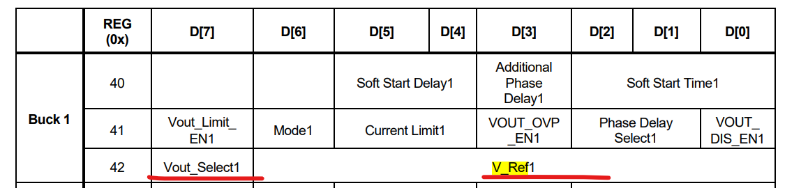
Output voltages are set using an internal reference Ref1 ranging from 0.55V to 1.82V, but what is The Default Value of Ref1? (First I will avoid using I2C communication and will rely on the default settings only.)
Some nice MPS tools are available for analysis of single MPS regulators, but I could not find anything for PMICs. Do you have tools involving analysis of MPS54304?
My plan is to use three of the MPS54304 buck regulators, so the forth buck output is redundant. For that 4th output I am planning to load it with 10k resistor and to connect a bulk capacitor of of 10uF. Does this sound reasonable to you?
Thank you for your time!
Zavarin