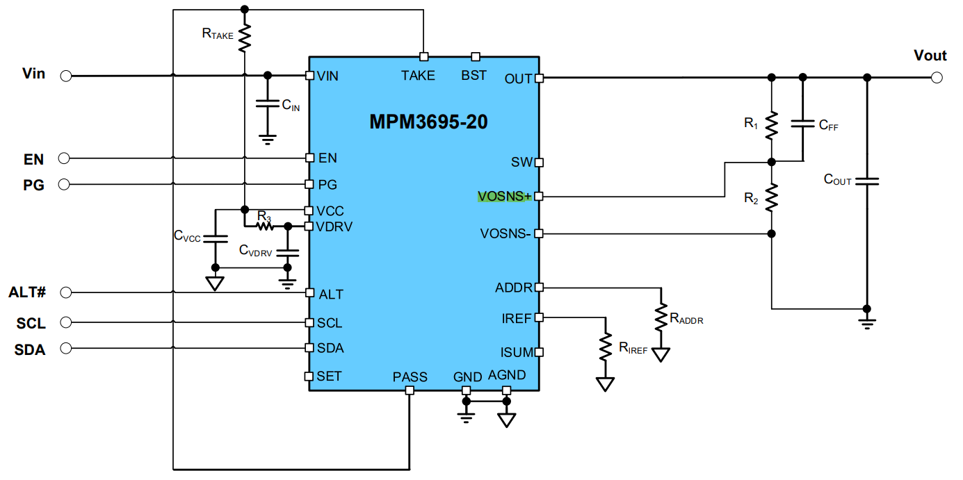
Regarding pin21 VOSNS+ in PIN FUNCTIONS from datasheet, what does it mean by “Connect this pin to the positive sense point of the load to provide feedback voltage to the system for remote sense”? Could you provide me a diagram pr explain?
In case we plan to use remote sense, Does it matter either internal voltage setting or external voltage setting? Can we go with external voltage setting when we go with external voltage setting.
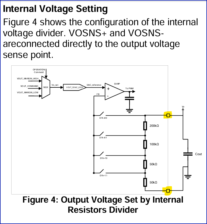
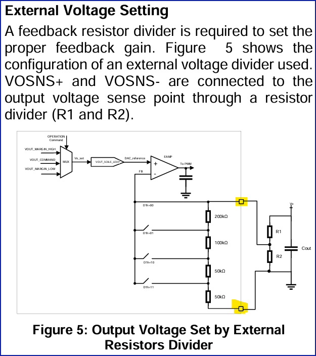
In figure 4 of datasheet, what are the definition of the pins that I highlighted? Also the same question for figure 5.
4. Take MPM3695-20 EVM as example, which node I should connect to remote sensing point? node 1 or node 2? And should I still mount R2 when I go with remote sensing? Finally, can we have a guide that walks through the remote sensing application?
You should be able to do remote sensing with both an internal and external resistor divider.
The highlighted nodes that you have here represent OUT and GND.
Use this diagram as an illustrated guide to connect remote sense but to also have the option for local sense as well. You should absolutely still need to have R2 added assuming that you are using an external divider to set your output voltage.
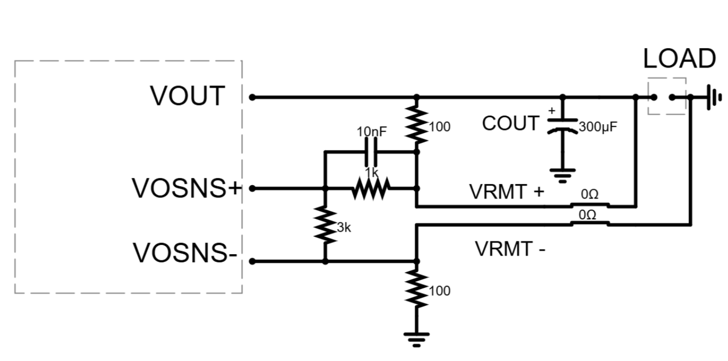
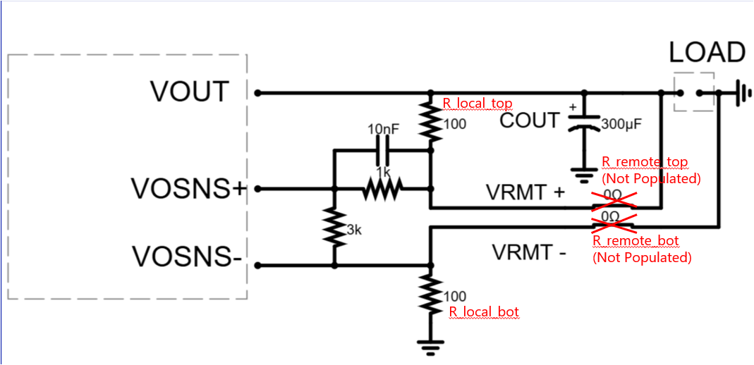
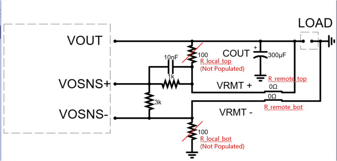
Thanks, please check if my understanding is correct. Resistors options for local sensing and remote sensing are mutually exclusive. The configurations are like attached:
(2) For remote sensing: ( Could you please suggest a value for R_remote_top and R_remote_bot? I have seen value suggested like range 10~50 ohm resistor in application from other vendor, but I don’t know the reason.)
Hello, sorry about the delay on my end with this request. Thank you for pinging me.
The diagrams of remote and local sense and your understanding on the architecture here is correct. Using this architecture allows for either option to be used if needed.
In terms of the actual resistors, the values do vary between 10 - 100 Ohms in typical applications. The choice of the specific value for your sense resistor depends on your application though. Do you have a high current you are sensing? Is this a noise sensitive rail?
Usually, a higher resistor value will minimize the voltage drop across the power supply therefore yielding sustained regulation at the cost of possibly injecting more noise into the measured signal.
For lower value resistors, you of course minimize power loss, therefore reducing thermals while also reducing your signal to noise ratio.
In essence, it really depends on what you are trying to prioritize for your sense application. I would encourage you to test with these values.