I am working on creating a single module which will power few 3.7V sensors
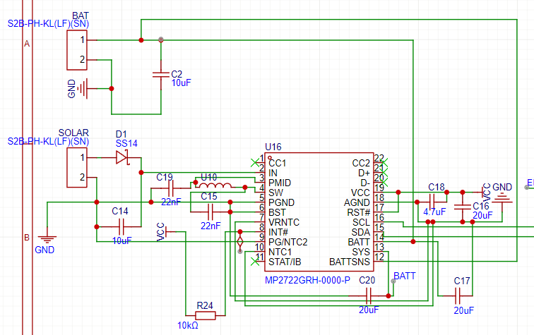
the module has 3.3V 2x1500mAh18650 Lithium polymer batteyries , that will be charge via 6V 150mAh Solar Cell. As A Charger i am using MP2722 and have made a cicuit
I would like to get any feedback as i didnt see anyone using MP2722 for such purpose. if i have made i correct Schema Thankyou
Here are some recommendations for the schematic that I have as it stands:
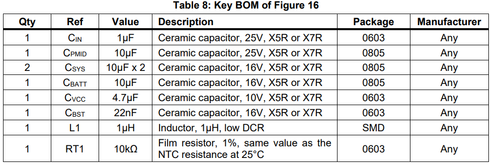
There should be a minimum of a 20μF ceramic capacitor from BATT to PGND. You currently have 10uF (C2) in place. You should have a 20uF minimum here.
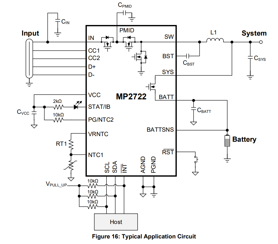
The BATT pin shouldn’t directly be connected to the output. This would undermine the functionality of the internal FET as seen in the typical application.
Since this is for a solar panel application, they can easily produce voltages above 6V, exceeding the max input threshold of this part. I would recommend choosing a solar panel with parameters where the Vmp (Max Power Point) is around 5V and the Voc (Open-Circuit Voltage) is below 6V.
On your layout, add test points in significant areas. This will make any debugging and just doing a general check on operation to be easy and accessible.