Hello,
I recently purchased the EVL4248-QV-00A evaluation board. However, I got stuck while developing my project.
To summarize : According to the datasheet, in order to enable the full output voltage range of 1 to 32(36?) volts, it is necessary to modify a resistor and the e-capacitors on the board.
For the resistor it is well explained but for the e-capacitors, it was a harder for me to understand.
Initially, I assumed it would be sufficient to identify the models of the existing e-capacitors and replace it with the same models but with a higher voltage rating. However, after reviewing the “Choosing the Right Output Capacitor” and “Choosing the Right Input Capacitor” sections in the MP4248 datasheet, I became a bit confused.
The formulas provided for calculating the required voltage and ripple current ratings yielded values that seem quite odd, and I haven’t been able to find a suitable capacitor that meets those requirements. This leads me to believe I may have made an error in my calculations or assumptions.
To summarize:
-
I am using an EVL4248-QV-00A board with an input voltage range of 5–20 V.
-
I would like to modify it to support an output voltage range of 1–32 V at the maximum allowable current.
-
I am seeking guidance on which components need to be changed.
-
Ideally, I would prefer replacement components that match the existing package types on the board.
-
If an exact package match isn’t available and any manufacturer’s components can be used, I personally prefer Würth Elektronik—unless you believe there is a better choice you can recommend me.
Best regards,
Alexandre L
Hello Alexandre,
Do you mind providing the calculations that you made for Cin and Cout? I am assuming that you are also going to be using the formulas on page 36 and 37 in the datasheet.
I am assuming you made calculations in both boost and buck modes and compared the ripple to some requirement that you are targeting. I am curious as to what voltages you are using since you are going through a range. I think since you are attempting to cover a wide range for the input and output while utilizing both buck and boost mode, it would be best to size these capacitors using the worst-case scenarios, which would be the greatest voltage differences in each mode for your application.
However, if you have any nominal target values, it would honestly just be best to defer to these if they are somewhere in the middle of the ranges you provided.
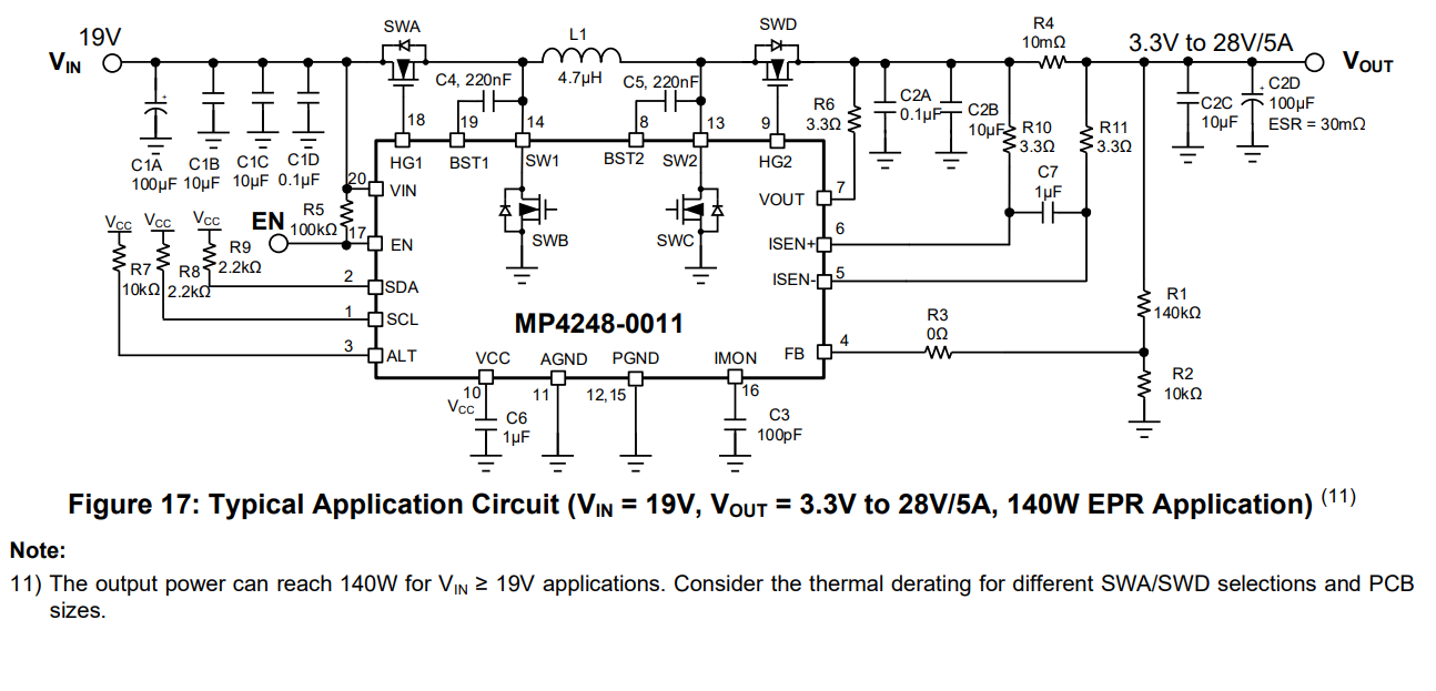
Also, if it helps, you can always defer to the input and output capacitors as used in this wide array application:
Hope this provided some insight.
Hello,
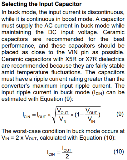
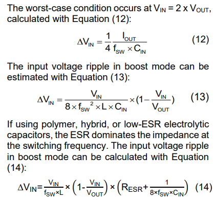
I used the formula on point (10) Icin = Iout/2 and got 2.5 amps ripple current, which is a lot higher then the rated ripple current for the input capacitor that is on the EVL4248, 1.7 amps for the EEHZK1V101XP. I got confused that the ripple current rating is so small and noticed the datasheet for the ELV4248 tells me to get bigger voltage rating which usually come with smaller ripple current rating. This is when I decided to come here as I felt stuck.
Also in the wide array application you just posted, what is voltage rating for C1A, and C2D, what is they ripple current rating, how are they different then the two that are already present on the evaluation board, why should I change them… ?
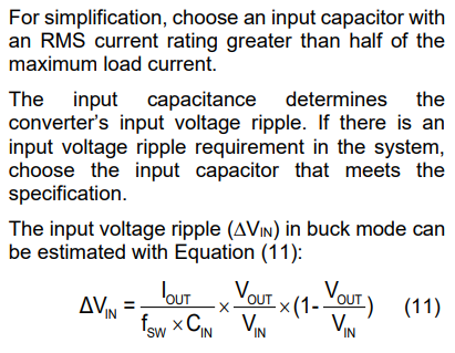
I am referring to this sentence on page 7 :
Hello,
During my time at MPS, we have always sized capacitors with this golden rule in mind:
A good rule of thumb for situations like this would be to get a capacitor that is 2-3x the rail voltage.
The reason why this is mentioned in the following note and why I’ve highlighted this golden rule is because of derating, meaning the nominal value of the capacitor changes in value based on variables like high temperature, voltage ripple, and frequency. These variables can add stress to a capacitor.
Different capacitor types (ceramic, tantalum, electrolytic, etc.) have different derating requirements, but the rule of thumb blankets the derating for all of these capacitor types with some margin. Generally, smaller capacitors will derate more easily, so this is something to keep in mind.
Having a capacitor rated at the exact voltage that is applied to a rail would likely cause some derating and therefore yield more ripple, where the fluctuations in voltage would lead to increasing temperature and stress on that component. You can typically find a derating curve of a capacitor on the datasheet.
Hope this provides some insight.
Best,
Krishan
Thanks for the update — it actually explains a lot. It’s basically the same rule as for the MOSFETs on the board.
I found a capacitor that meets all the conditions: the EEH-ZU1J101P from Panasonic. I’ll replace both capacitors on the board with two of those.
I also decided to change the MOSFETs for one with a higher voltage ratings, the AO4262E from Alpha & Omega.
And of course I will have to change to resistor in the divider circuit.
So my last question is : Will that be enough to unlock the full voltage range (at least 1–30V) with Vin between 5–20V, while still supporting the maximum current?
Did I miss anything?
Best regards,
Alexandre L
Hey Alexandre,
Good note on the FETs and of course the feedback resistive divider. I think this should cover everything such that you should be able to use this IC at its full intended capability. I would recommend testing this just in case.
If there are still any limitations, please reach back.
Best,
Krishan
Hello again,
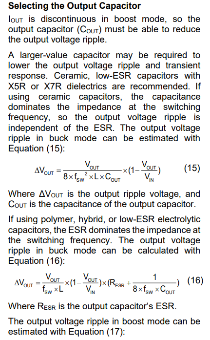
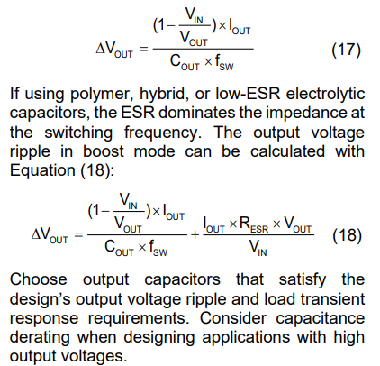
I was actually doing some tests and realized that I cannot find anywhere in the datasheet what is the current rating for the output capacitor… Is there a formula for this ? I took the same capacitor as the input one for the output but I am not sure it’s was actually 100% right. I am using a 12 mOhm, 4.6 Amps at 100kHz capacitor, is that ok ?
Best regards,
Alexandre Leviev
Hello,
This would ultimately depend on the load current that you will be expecting. It would be safe to give yourself a 6A-7A rated capacitor here if needed for a sure safe threshold for headroom since this IC is capable of load currents up to 5A. Hoping these ratings accommodate well with the footprint of your design.
If 4.6A is relatively 0.7A - 1A more than your expected average amperage here, then this would mean I’d see no issues with the capacitor you have chosen. Have you implemented this and tested the IC with this?
Hello,
I didn’t expect it to be that straightforward. I thought it would be more like calculating the input capacitor (Iout/2). I haven’t tested the prototype at high current yet, but it works fine at moderate loads of around 2–3 amps.
My goal is to push it up to 5 amps, so I’ll replace the output capacitor with one rated for a higher ripple current (at 100 kHz or above). For now, for testing purposes only, since I don’t have a suitable capacitor on hand, I’ll place two EEH-ZU1J101P capacitors (rated 4.6 amps at 100kHz) in parallel on the output and test it at 5 amps.
Best regards,
Alexandre L
You could go the exact route and make calculations. I am just going off of percentage margin thresholds which would give you headroom above the expected calculations needed. Let me know how testing goes.