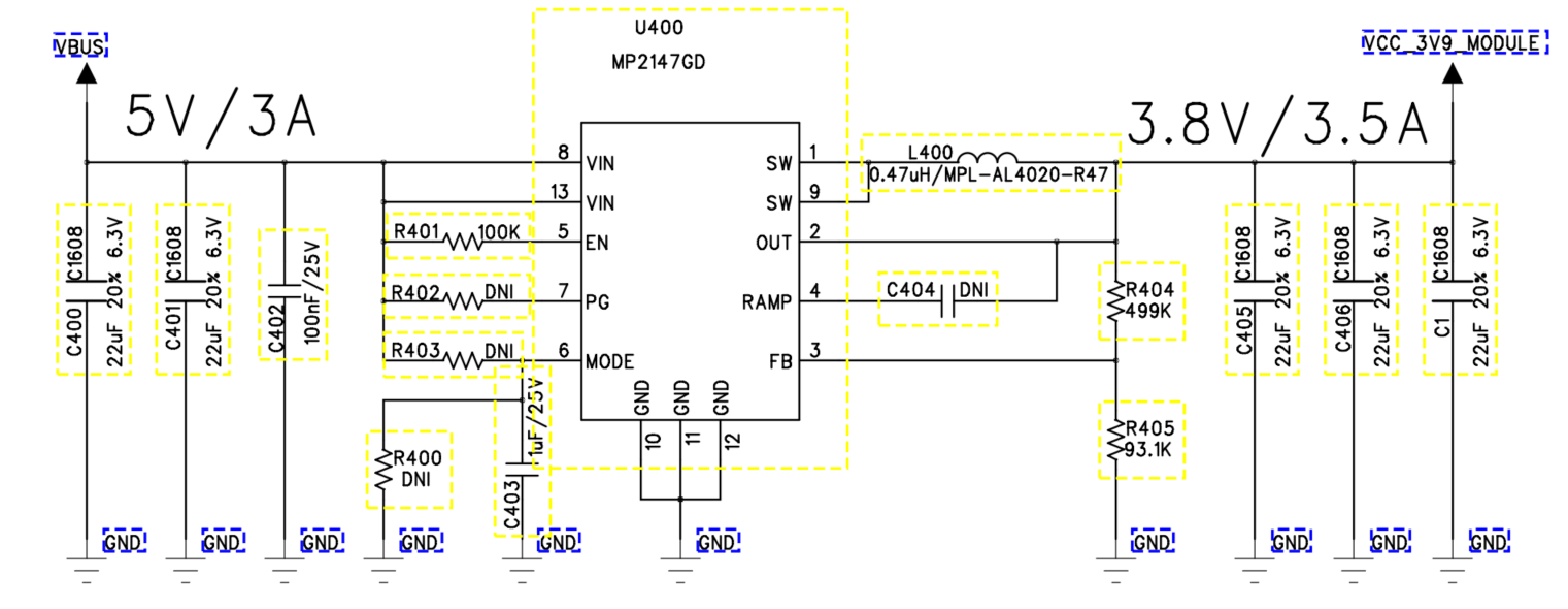
Hello, I designed a circuit using mp2417 with input=5v, output=3.8v, and power path management system. I am ordering the PCB first and verifying the circuit, but it is malfunctioning. Please verify the circuit.
While I verify the design, what is the malfunction that you are seeing exactly?
Since I don’t have EV B’d, I directly connected the parts to MP2147 with enamel wire and tested it. When I connected a 3ohm simetent resistor on the load side, the IC burned out due to overcurrent.
If there is a reference circuit in the datasheet for how much the enable resistor value should be / how to connect PG / how to connect MODE, etc.
I would like to receive it.
Hello,
As of now, there isn’t a reference circuit outlining an output of 3.8V @ 3.5A specifically, but this typical design in the MP2147 datasheet may be of some insight (page 18):
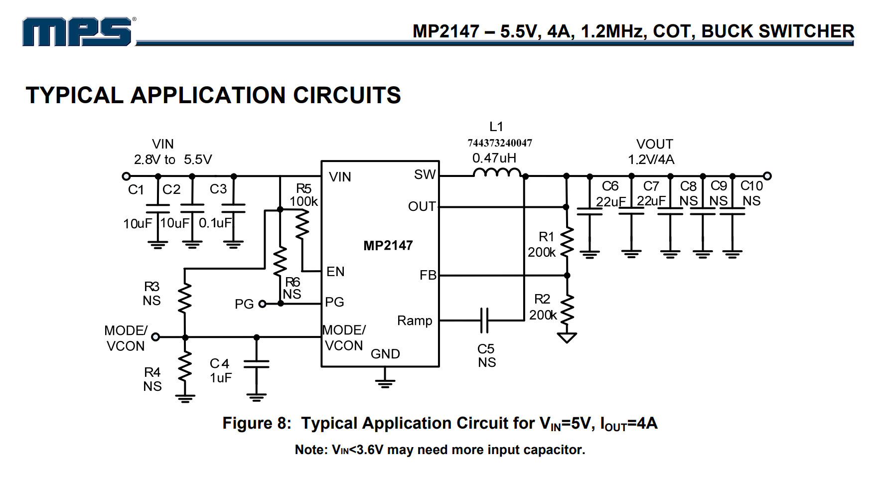
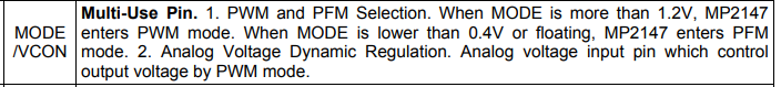
There doesn’t seem to be anything wrong with the way that you have connected your components with the schematic that you have sent. The above schematic should serve as a reference circuit in the datasheet for how much the enable resistor value, connecting PG, and how to connect MODE (the image below shows what voltages dictate the operation mode your circuit is in, please use this as a reference to verify that you are in the correct one).
Since you have an input voltage greater than 3.6V, you may want to increase your input capacitance a bit more. This should dampen anything at the input such as current spikes at this stage.
Finally, as a sanity check, it is always good practice to check the voltage requirements of the load. And be sure the connections with the enamel wire as you have connected them are the proper AWG and current rating as well. An EVB would certainly be a more reliable way of testing this part and swapping out components to achieve your desired output.
Hopefully this helped.
Best,
Krishan
Thanks for your answer. However, I have some additional questions:
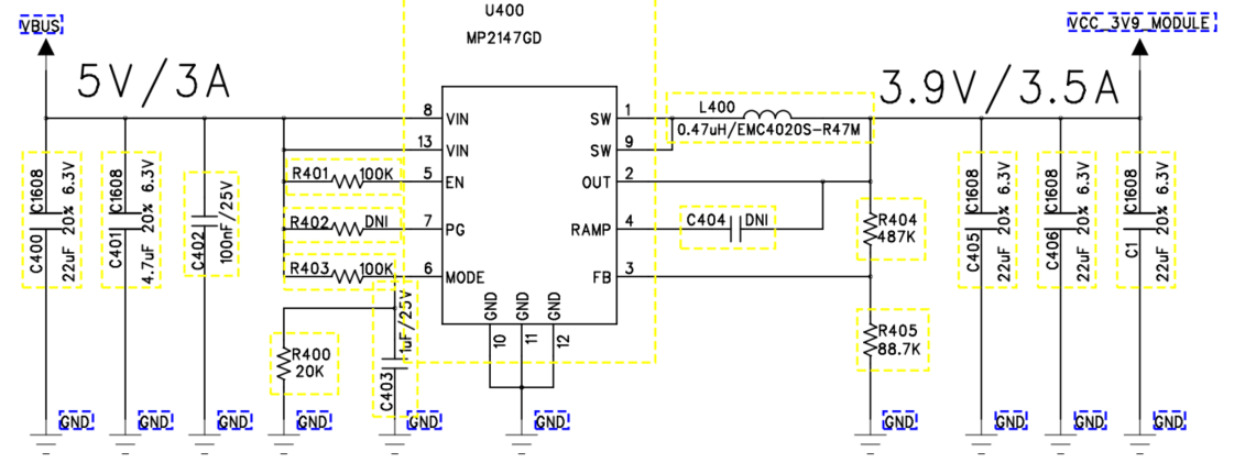
‘MODE/VCON’: Connected to about 0.8V with a 100K/20K voltage divider.
- Is this connection correct?
- Otherwise, should I input more than 1.2V with the voltage divider?
- Or should I connect a 1uF capacitor in parallel and leave the voltage open?
'PG: Not connected to DNI.
Regarding ‘MODE/VCON’, should I divide the input power with a resistor to input 1.2V or can I just connect a 1uF?
IN: 5V/3A (USB powered)
Out: 3.7~4V/3A
Is there a reference circuit that can output like this?
The PCB is made, so I need to use MP2147 or MP2145.
To answer your questions in the following bulleted order:
- Yes, the MODE/CON connection is correct.
- Assuming that you want PWM mode, having more than 1.2V on the voltage divider would suffice by dividing your input power in this case.
- If you leave the voltage open, you will be in PFM mode, which is better suited for light loads which it seems is not the case for your 3.9V @ 3.5A output application.
Unfortunately, the only reference that we have in the datasheet has been posted in Figure 8 above.
But I would say that using the MP2145 would be best to give your output current some headroom. Also, it is worth mentioning that your efficiency would certainly be higher when operating in PWM mode.
Best,
Krishan