When MP3398E is operated in slave mode, how should the output channels be connected?
Should the output pins of the master and slave ICs be connected in parallel, or should they drive separate LED strings individually?
Hi @nickbin09, thanks for contributing to MPS Technical Forum.
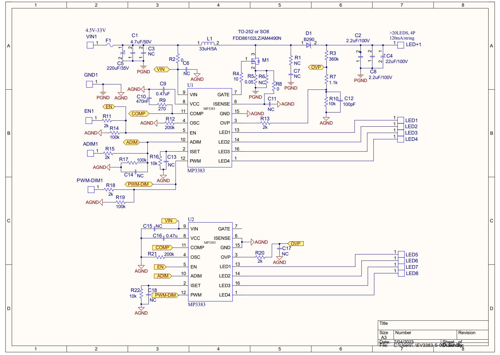
We recommend using the MP3383 to replace MP3398E since MP3383 is the next generation of MP3398E with better current matching performance, and there is a pin-to-pin compatible option.
Attached is the schematic of two IC cascade application. If you have a detailed application spec, we can help provide a customized schematic too.
Thank you, Will
Hi William,
Thank you for your help in responding to our questions.
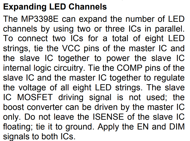
Currently, we have not used the following circuit configuration with the MP3398E. According to the datasheet, the MP3398E can be configured in Master/Slave mode to expand the LED channels (from 4 to 8 channels). However, on one of our PCBAs, we observed that the MP3398E is designed using the above configuration, but each LED channel of the two LED drivers is connected in parallel (i.e., Master_LED1 is paralleled with Slave_LED1, and so on), instead of routing out eight independent channels. Could you please advise what the advantages of this design approach are?
I do not understand your configuration. Are you able to share a schematic capture? Thank you.
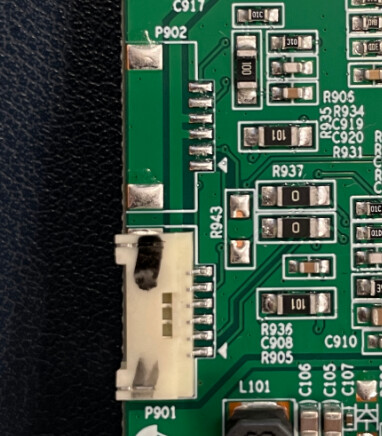
Sorry, we do not have the schematic available at the moment. The following understanding is based on our analysis of the existing PCBA.
The LED channels of P902 and P901 are connected in parallel.
We recommend routing each of the eight LED channels independently as shown in the schematic above.
Thank you, Will