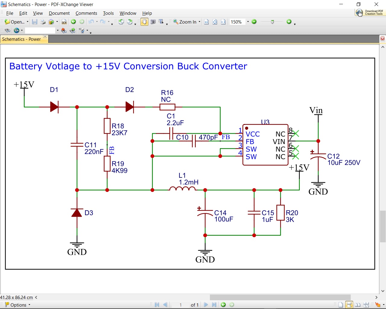
I am currently using the MP9488 step-down regulator but am experiencing two problems that are probably related. This is what I have discovered with the design that is almost identical to the one shown at the back of the data sheet for this part. I have attached the schematic.
When the circuit is powered down, the 15V output from the regulator starts to oscillate at a frequency of about 5Hz where the output swings between 0V and some upper limit which decays over time. When there is very little load, 3K-ohm, the oscillations do not occur, however, under normal operating load conditions where the regulator is supply approximately 100mA, they do. This in turn causes other supply rails, such as 5V and 3V3 to oscillate and cause multiple underisable CPU resets etc.
Again, under very little load, 3K, the output voltage from the regulator is about 15V as expected. However, under normal loading of about 100mA the output supply drops to about 12V. Placing a 220R load across the output drops it to less than 10V while it is only supply about 70mA.
Can anyone suggest why I am seeing power-down oscillations and poor regulation?
I have since done a bit more investigation into the problem and have found that the regulation works correctly when I use an input voltage of 40V or higher. I was originally using 30V. I have noticed that between 30V and 40V the output voltage is not as calculated, but is after the supply gets to about 40V.
As the device is rated for an input voltage as low as 7.5V, what would I need to change for this circuit to operate at 30V?
In addition, when the input supply drops to below about 9V the output swings between 0V and 9V etc. It appears to do this every second or so and I am wondering if this is because the device has switched off due to under-voltage.
How do I calculate the shut-down period for this circuit configuration?
Is there a way to prevent restarts after the device has shut-down for the first time?
I our application we will need to provide the regulator with a voltage supply from a 120V D.C. battery.
The MP9488 is a step down (buck) regulator only, which means that the input voltage has to be higher than the output voltage to allow it to “step” Vin down to Vo.
Buck converters typically create a type of PWM signal on their switch node (the SW pin), which is then filtered through a low pass LC filter composed of the inductor and output capacitance. This PWM signal is swinging between Vin and GND. If the duty cycle of this PWM signal is 50%, then the output voltage will be 50% of Vin. If it’s 100% (theoretically), then the output will be 100% of Vin. This basically just means that Vin always has to be higher than Vo. That’s why you see the output going to 9V when Vin is 9V, even though Vo is set to 15V.
In your application where you need 120Vin and 15Vo, this shouldn’t be a problem. I’m not very familiar with battery voltages of that value–what’s the lowest battery voltage you expect?
After checking this on an eval board, we can support an output voltage of 15V with a load current of 100mA when Vin is at least 20V. If Vin decreases from here, then Vo will drop with it. This was with a 68uH inductor.
It looks like the lowest voltage from the battery could be as low as 28V (from memory - I will need to double check) when it has been placed into standby mode. In that mode certain ICs will be disabled but the CPU will still be operative. I will determine what our exact current requirements are when we are operating at a reduced voltage and let you know.
What evaluation board are you using, I was not able to find one for this device?