If want to know how big the input bulk capacitor should be to smooth the input voltage ripple.
I couldn’t find this information easily.
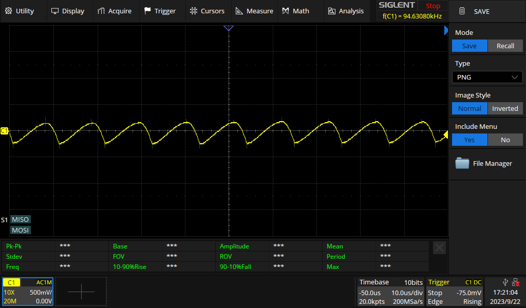
Currently I have about 500mV p.p.
Is that large or enough to ensure safe operation?
If want to know how big the input bulk capacitor should be to smooth the input voltage ripple.
I couldn’t find this information easily.
Currently I have about 500mV p.p.
Is that large or enough to ensure safe operation?
1% ripple then? That seems OK, cut it in half and see if your circuit malfunctions, then cut it in half again see if the circuit malfunctions…
The limit on the high side would be dissipationI in the PD switch that operates in a linear region as the bulk cap is charging up. Make the cap big enough and the PD switch blows, so try doubling the cap and see what happens, then double it again.
i find it useful sometimes to refer to the eval board or the reference design schematic. In principle that has been built and tested by somebody skilled in design who also has access to the IC designer and other experts in the field.
The ripple you are seeing is probably more dependent on the previous stages output capacitance.
The input capacitor will suffer self heating due to the ripple, it will also have to deal with the current spikes while charging/discharging.
so…
1/ Does the minimum measured voltage approach the drop out voltage for the device (with a safety margin)?
2/ Does the current exceed the capacitor current rating?
3/ Does the expected temperature rise exceed the capacitor temperature?
4/ At operational temperature, does the capacitor life decrease beyond the expected product life?
note:
Capacitor life is approx:
These are approximates, but will give results to make selection of Electrolytic caps. Ceramics are the same, but have very high currents and low self heating.
Simon