Hi I am considering parts for the design of a combined charger and boost circuit.
Hard Requirements are:
1 cell Li-Ion battery, maybe 18500 or perhaps a couple of 14500 in parallel.
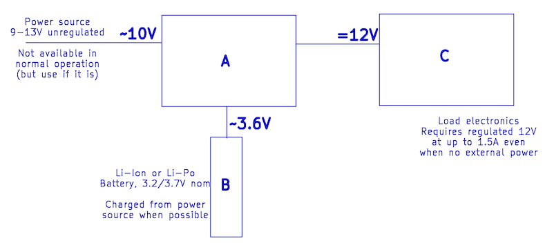
Non-battery power source intermittent, range 9V to 13V.
Output (sys load) 12V, regulated. Will be supplying other circuits including MCU which should not be reset, so no glitches.
Output (sys load) current. Hard to pin down, but min 300mA, likely “normal” 600mA, and peak about 1.5A (expected for <0.5s). However this is not well defined and “normal” could be 800mA or peak be higher or last longer than 1s.
Desirable:
Charging happens whenever possible, whether load is powered or not.
Input power voltage glitches are possible - manage with caps?
Battery cell undervoltage as well as overvoltage protection. If cell undervoltage and no input power then output is off.
Battery cell disconnect option: need to completely disconnect cell power, so no cell load at all. By default this would be a mechanical switch, but a small pushbutton would be easier to fit and allow a timeout shutdown.
Having looked through MPS ICs the MP2770 looks sensible, but the way I see things I need 3 distinct power attachments: one for the cell, one for power in, one for load, because power-in needs to be regulated before use as load power. I can’t see how you would configure the MP2770 to do this?
PS. a 2S cell option would be interesting, as would LiFePO “flatpack” cell, but the enclosure is very constrained.
PPS I have a prototype using a buck converter (power in 12V->5V) feeding power to a 1-cell to 5V buck-boost charger, feeding power to a 5V->12V boost converter. It doesn’t work I think because of transient power limits exceeded by the load. Unfortunately the load is not my circuit.
From what I have read, here are my thoughts on the MP2770 for your application:
If you can size the cell and MP2770 such that the battery alone can handle worst case peaks, then the MP2770 is a fine choice. Since you mentioned glitches at the input (9V - 13V) then I’d recommend a ceramic cap (around 100uF) and a TVS diode at the input for dip suppressions and spikes.
If you want the system to dynamically bypass the battery with external power available, the MP2770 may not easily do this alone. An external load sharing or power path management circuitry would be needed then.
Here are other options that I would personally use if I wanted to support a buck-boost topology and dynamic power path management.:
Hi Krishnan, thanks for your reply.
It is interesting you mention the cell handling worst case peaks, because that seems to be an issue in my testing so far (not using mp2770!), which was unexpected given an 18650 cell as source.
I don’t want or need source power passthrough, because the power source is not sufficiently regulated and I don’t want to expose the downstream components to its vagaries. Ideally the MP2770 will do that regulation.
Can you comment on the question I posed above: “I need 3 distinct power attachments: one for the cell, one for power in, one for load… [snip] … how you would configure the MP2770”?
All load power goes through the battery boost path. The MP2770 doesn’t support direct source to load passthrough or prioritization.
If the MP2770 is used, then I would recommend adding a 9-13Vin to a 5Vout buck before IN. Use large ESR caps near VOUT to handle any bursts and confirm that the boost design supports the 1.5A peak at 12V.
If the battery peak current is insufficient despite the 18650, then consider a higher discharge cell or a dual 14500 in parallel. Or use a buck-boost charger with dynamic power path like the MP2759 where input power can be routed to the load or battery.
I’m attempting to identify what parts are in box A
Box C is predetermined, and box B is the battery.
I had hoped from the datasheet description that there was a way to use MP2770 but this is looking unlikely given what you report.
I was hoping to find one ic that would do it all, given this is surely a common need. The best I can think of at the moment is to take the MP2770 battery/syspwr pin and use a boost converter to jump from ~3.7V to 12V. It is my understanding from the datasheet that the 2770 can accept the 13V input even if it’s charging one cell at 3.7V? Is this correct?
Correct, you can directly connect the 9V - 13V unregulated input to the MP2770 VIN pin. The MP2770 will regulate this for batter charging via the BAT pin. The charger won’t pass the input voltage directly to SYS, which is ideal in this case.
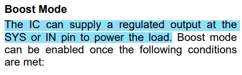
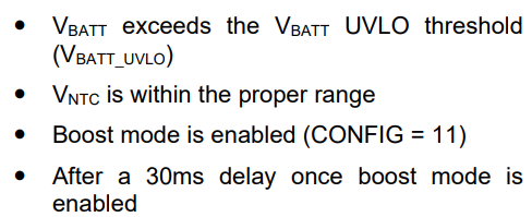
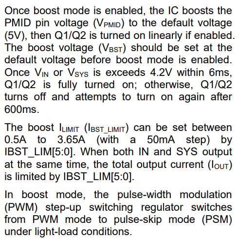
Did some reading and here is what the datasheet has to say about the regulated output for boost mode:
The MP2770 can boost up to 3.65A, but at lower voltages. Boosting to 12V @ 1.5A means an 18W output, meaning you will be pulling 5.5A from the battery at 3.7V since you are using a single 18650 cell. This would be right at the limit considering thermal and conversion loss.
The block diagram you have would need to be tested to validate thermals here or at least limit the IBST_LIMIT output current limit just to be safe. So, while an external boost may not be needed, but it would be effective if more headroom is needed.
Sorry about the confusion. The MP2770 is still capable here, but I would check the following before moving forward with this design. Let me know how testing goes in that case.