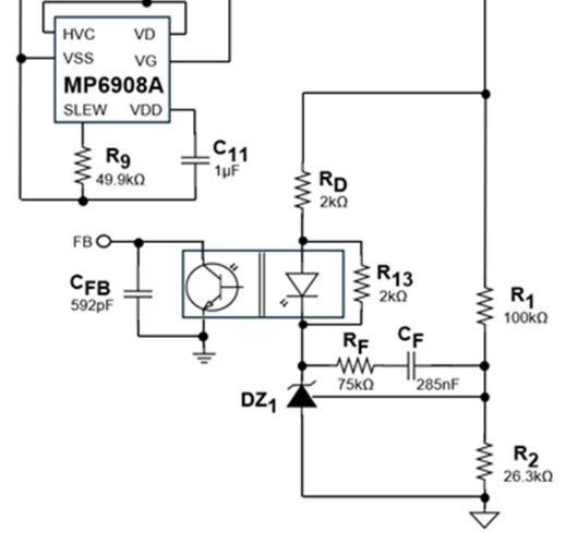
In “How To Design A Feedback Loop Compensator For A Flyback Converter In Four Steps”, Article #0137, referring to Figure 4, what is the purpose resistor R13 that shunts the opto’s LED? This resistor is also referred to as Rbias in Figure 3.
There seems to be no mention of it in the article’s text.
Hello Anthony,
I see that you are referring to Rbias in the following figure in the article you just referenced:
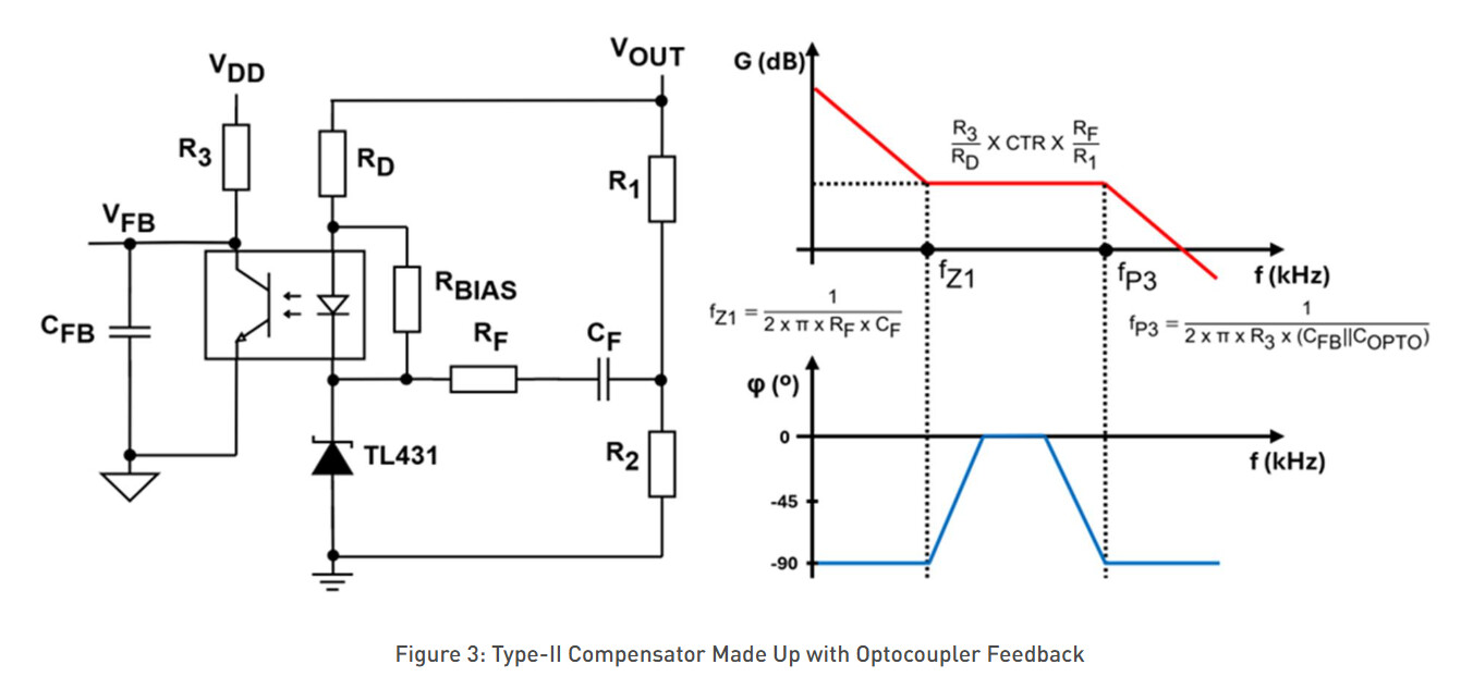
This is a really good question. Especially more so that none of the equations here seem to go into detail on how to size this resistor.
From what I know about the compensation networks of an SSR Flyback, this Rbias resistor limits the current going into the optocoupler diode. By doing this, you also limit the amount of emitted noise as well.
This forum post on stack exchange dives deep into the mechanics here as well if you are interested in more reading here: power supply - Resistor parallel to optocoupler LED in Zener-stabilized circuit - Electrical Engineering Stack Exchange
Usually, Rbias is some value like 5kOhms or less (this varies with every implementation). It looks like by the end of this design as detailed in this article, this resistor is 2kOhms (denoted by R13):
Let me know if there are any additional questions here. Always happy to help.
Best,
Krishan
This topic was automatically closed 90 days after the last reply. New replies are no longer allowed.