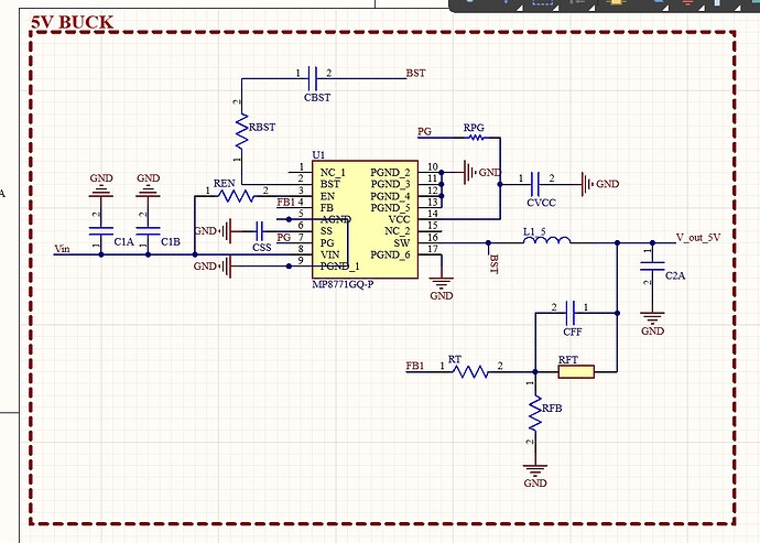
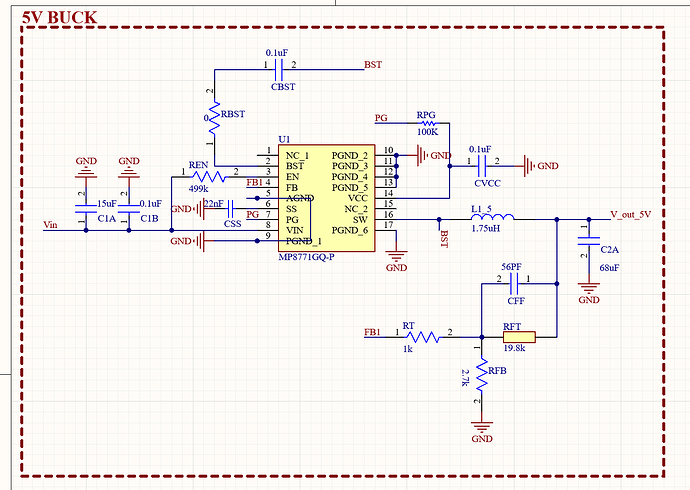
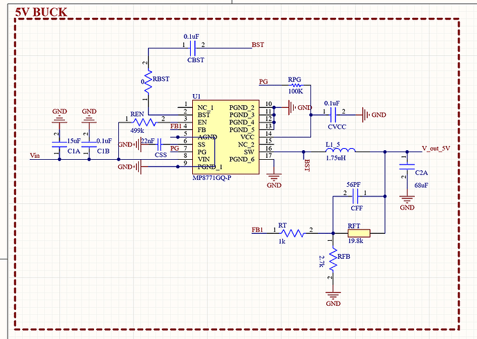
Project Overview: I am using an MP8771 to step down a 14.4V battery pack to a stable 5V output. The design was initially created using the MPS DC-DC online tool, then transferred to Altium for PCB layout. This PCB is a 2-in-1 design with:
- An MP8771 buck converter for 5V output.
- A separate buck-boost converter for a 12V line.
Issues Observed with MP8771 Circuit:
- Output Voltage Incorrect: The MP8771 is only outputting 2.5V instead of the expected 5V.
- Feedback (FB) Voltage Low: The FB pin reads 0.3V, while it should be 0.6V according to the datasheet to achieve 5V output. This lower FB voltage aligns with the lower output voltage (2.5V) according to the feedback equation, but adjusting the resistor divider to compensate did not resolve the issue.
Troubleshooting Steps Taken:
- Resistor Divider Check:
- Verified and adjusted the feedback resistors to achieve the target output voltage of 5V, but even with modifications, the output remained at 2.5V. For example, changing the top feedback resistor (R1) to 40kΩ had no effect on the output voltage.
- Component Checks:
- Double-checked component values and connections for all key components (feedback resistors, bootstrap capacitor, input/output capacitors, inductor).
- Ensured that R1 and R2 values match the recommended values for a 5V output (20kΩ and 2.7kΩ respectively) but saw no change in the output.
- No-Load Testing:
- Tested the circuit with no load connected to the output, but the output voltage remained at 2.5V.
- IC Replacement:
- Suspected a potential issue with the IC, so replaced the MP8771, but observed the same behavior.
- Power Supply and Grounding:
- Verified that the input voltage (VIN) is stable at 14.4V and that the EN pin is correctly pulled up to enable the IC.
- Ensured proper grounding on the PCB and verified PCB layout for any potential issues with high-current paths.
- Over-Current Protection (OCP) Hypothesis:
- Considered that OCP or another protection feature (like Short-Circuit Protection) might be activating, which could cause the MP8771 to enter a hiccup mode. However, the IC doesn’t show typical symptoms of hiccup behavior (no cycling on/off).
Key Observations for Forum Readers:
- FB pin voltage is consistently at 0.3V instead of 0.6V, even after adjusting the feedback resistors.
- Output voltage remains at 2.5V, regardless of adjustments to the feedback network.
- No external load on the output during testing, so load-induced voltage drop is unlikely.
- Components have been checked and are correctly rated for the current and voltage requirements of the circuit.
Questions for the Forum:
- What could cause the FB pin voltage to remain at 0.3V despite having the correct resistor divider values?
- Could there be another factor (e.g., grounding, layout, or hidden internal fault) that would prevent the output from reaching 5V?
- Any specific tests or measurements that could help diagnose whether protection features (like OCP) are triggering unexpectedly?
Any insights or suggestions to help troubleshoot this issue would be greatly appreciated. Thank you!


