Hi all,
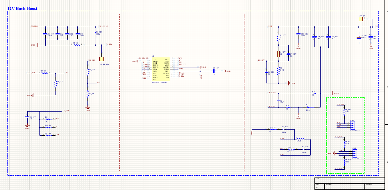
I have a quick question regarding a board I just built to supply 12V at around 5A using the MPS 4245. I’m using the schematic attached below and haven’t programmed the chip yet because I want to confirm whether the observed behavior is normal:
- Unprogrammed output voltage: 2.8V
- EN pin voltage: 4.49V
- Pull-up resistor for programmer pins: 5.22V
Do these voltage levels seem typical? Any recommendations or insights would be greatly appreciated!
Thanks in advance!
Hi Giosef,
Thanks for reaching out on the MPS Forum. SCH looks OK, but I have a recommendation. See below.
The configuration I see has been set up for 5V output for the -0001 version. An issue I see with the schematic is the FREQ pin is being pulled up with a 0 Ohm. For pull up resistors, I would recommend using a larger value (typ 10k).
The default configuration should come up at 5V, coming up at 2.8V indicated there may be something wrong with your feedback network and/or reference voltage. You should look at your register setting and ensure the GAIN, VOUT_COMMAND and VOUT_SCALE_LOOP are all in agreement to output your desired voltage of 5V first, then adjust for 12V.
To verify that it is working correctly, check the Output voltage waveforms, FB voltage, and SW node are all in agreement. You can also monitor all the settings via the Virtual Pro Bench GUI
Virtual Bench Pro 4.0
Thank you Stephen,
One more question, if I were to program this with an Arduino Nano (instead of the programmer) and the Virtual Bench, do you know how I could go about doing this?
You should be able to program using the I2C functionality on Arduino. You may need to obtain a PMBus library from GitHub or other repository. PMBus is based on I2C Protocols. Here you should be able to access and read/write to registers.
I would recommend obtaining our programming dongle and VB Pro, from the GUI you can adjust registers and save to memory without having to develop your own code. From the GUI you can export the I2C registers to be used by your MCU.
1 Like
Hi Stephen,
Good news! I’ve successfully programmed the chip, and it’s consistently outputting 12V. However, I’m running into an issue where it resets once the power is removed from the chip and it goes back to its 5.0V ouput state. Is there any code I could write to ensure the chip continues outputting 12V, even when it’s powered on or off?
Here’s the code I’m currently using:
#include <Wire.h>
void setup() {
Wire.begin(); // Initialize I2C bus (address optional for master)
}
byte x = 0;
void loop() {
Wire.beginTransmission(0x61); // Transmit to device #8
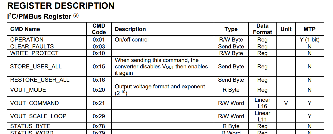
Wire.write(0x20); // Send control byte
Wire.write(0x00); // Send parameter byte
Wire.endTransmission(); // End transmission
Wire.beginTransmission(0x61); // Transmit to device #8
Wire.write(0x21); // Send control byte
Wire.write(0x000c); // Send parameter byte
Wire.endTransmission(); // End transmission
// x++;
delay(500);
}
Thanks again for your help!
Best regards,
Gio
Hi Gio,
Glad to hear you have been able to successfully program the IC.
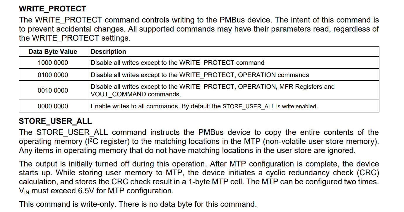
Sounds like you are writing to the volatile memory, which resets upon power cycle. To program the IC, you would need to program to our MTP (multiple time programmable memory). You can write by accessing STORE_USER_ALL. See page 26 on datasheet.
1 Like