Hello,
I have 2 x MPQ8875A connected to the same 3.3V I2C bus. I am using the Python3 smbus2 library to program and query all my devices.
First, can you please confirm my understanding:
- Bring the EN pin of one device low shuts down Vcc (I see this on an LED) which powers down the I2C pull-down transistors, allowing me to program the OTHER device.
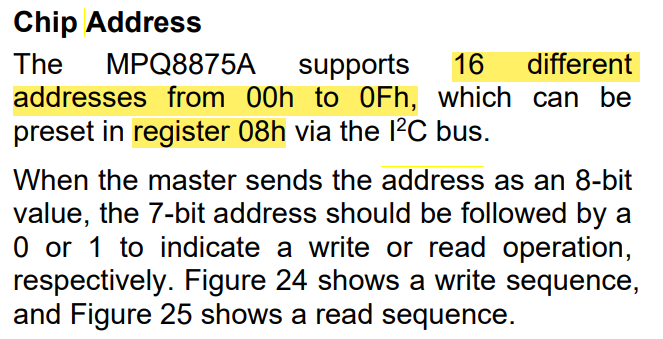
- The default slave address for the unprogrammed part is 0000_000 (same as the general call address?)
- Sending 0x00 0x08 0xA0 should program a device with slave address 0x0A
This isn’t working: the following command results in Errno 107: Transport endpoint not connected:
bus.write_i2c_block_data(0x00, 0x08, [(address & 0x0F) << 4])
There are many other devices on the bus and some of them will respond to the general call address (for example, reset command 0x00 0x06). However, efforts to program this address are failing.
A second question: how do I AVOID programming OTP registers? We want to be able to control output voltage dynamically from software. Which registers are OTP and which can be written repeatedly?
Hello,
Apologies about the delayed response on your questions. In response to what you have written, I would like to understand a few things:
- Your numbered list of understanding is correct according to the datasheet.
- I first wanted to ask if there was a suffix on your MPQ8875A ICs?
- Since you are using 2 identical MPQ8875A ICs, are they configured to the same address? This may complicate the program data sending process
- Have you tried writing to these ICs with independent I2C lines via flywire perhaps?
As for giving a direct answer for whether or not you can completely avoid programming OTP registers, this would mean that you would have to write to these registers via volatile memory to keep dynamically changing the output voltage. Since you are using Python3 smbus2m, it would really be a matter of just paying attention to read/write registers and write registers only for those corresponding to setting the output voltage.
I look forward to hearing from you such that we may solve this issue.
Best,
Krishan
Hi Krishan,
Many thanks for your response. Thank you for confirming my understanding.
- Suffix on parts is 0000 for both-- so yes, the address is the same.
- Unfortunately there is no fly lead or even removable resistors on the board to make a direction connection to a single part-- both parts are connected on the same address
- I am pulling the EN low on the part I do not want to communicate with
How can I “write to these registers via volatile memory”? I have been through the DS a few times and don’t understand what I2C writes will land in volatile vs OTP memory. Can you point me to where this is specified or even share some sample code or source code for your programming utility?
So if I understand you correctly, what I am attempting to do (shutting down one part using EN in order to program the address on the other) should in fact work correctly and the fact that it doesn’t means there could be an electrical issue. But I am also wondering if the slave address being 0x00 is simply not understood for normal writes on my system. And further, not understanding how to control if I am writing to OTP or RAM leaves me with some doubts.
Hello again, can you please provide further clarification in response to my message above? Still trying to get this issue resolved.
Dave
Hello again, I’ve been meaning to respond to this request with low bandwidth, thank you for your patience.
You can write to volatile memory when using the GUI for testing purposes. OTP programming involves non-volatile memory programming where the default values would be changed as you know. If not through the GUI, I would contact the engineers at MPS directly in order to get sample code for this: Contact MPS - Contact
Please read the following application note on OTP programming for this IC as it would certainly provide some insight: AN175 - MPQ8875A: Configurable, 4-Sitch Buck-Boost Automotive Controller
On paper, your understanding is correct in that shutting down one part using EN in order to program the address on the other should work. I can recommend the following to isolate this from being some electrical issue:
- Check the I2C Bus Activity
- Verify that the MPQ8875A is responding at all when one device is disabled.
- Confirm that the general call (0x00) commands are actually being sent and acknowledged.
- Manually setting the I2C address
- If relying on the general call (0X00) is not fruitful, consider directly addressing the device directly if possible or using different addresses for different devices assuming that general call writes is not handled well.
- Ensure EN Pin behavior is actually disabling one device
- I suppose pulling EN low may not immediately remove the device from the I2C bus if the internal pull-downs are weak.
- Remove power from the unwanted device to confirm it is truly disabled for each device just to test if this can be done.
Let me know how testing goes with the following info in mind. Apologies again for the latency on my end.
Best,
Krishan