Hello, I am using the MPQ8634BGLE to create from 12V to 5V@18A.
unfortunately, the MPQ8634BGLE at 10A starts working bad.The output voltage is around 3.5V and the current is jumping between 7~10A. I tried to change the CBF RCS and RMODE to try different modes and also I changed the FB resistors for 1V output like the EVB.
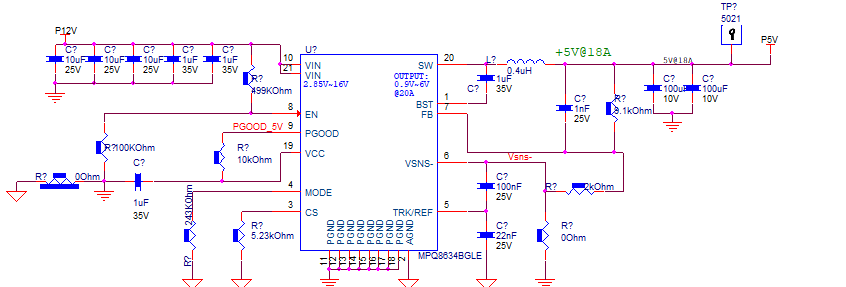
attached schematics.
Hi Ron,
Thank you for utilizing MPS Technical Forum,
I have looked into your circuit, things do not seem wrong connection wise. I compared your schematic with the EVB too - looked similar with variance on component values.
I think the inductor should be re-calculated and higher value should be used, what frequency are you using and which mode are you implementing?
The EVB is optimal for the 1V Vout, it was not designed for higher voltages. However, the Eval board can be used to swap components and test for higher voltages and perform testing to best fit your requirements.
Dear Nouman,
Thank you for the reply,
We also tried working with a 4.7uH inductor, but it did not change much.
I read the datasheet and it does not say 5V will not work at high current.
In fact, there are graphs with VO = 5V.
We tried the MPSmart 8.4 simulator and the simulation works with output voltage 5V@18A.
There is no EVB for purchase to debug the problem.
Can you please help us to re-calculate the RLC to fit our requirements?
Hi Ron,
Yes, I can assist with confirming the results obtained in the re-calculation. Are you implementing FCCM mode? and please confirm you have a proper feedback loop and connection for stable output voltage result.
In your initial post, you mentioned you changed couple components, were you able to replicate results similar to EVB 1V vout?
Hi Nouman,
We tried all the configurations FCCM and Pulse-skipping.
We configured our design for 1V output we cant consume more than 10A.
If we consume more than 10A the voltage drops to 0.3V~0.7V and as I mentioned before, the current starts to fall and jump between 5 to 7A.
Hi Ron -
My apologies on the late reply. The schematic for a 5V Vout is very similar to that of 1V shown above. The difference is what divider ratio is used in the feedback network.
I noticed you are using 8k and 2k divider. Can you please try a higher resistance value for both of the resistors? and confirm if you are still having issues with the output?
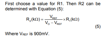
Using the equation above from the part datasheet - I calculated approximately 27kohms for R2, and chose 120kohms for R1. You may test on these values.
Also another suggestion is to try test it without the 1nF cap as it might be shorting the output to the FB pin.