Dear MPS team,
I am planning to use MPQ8632-6 DC-DC regulator to generate 3.3V and 1.8V in my design. I have done the design using DC-DC designer tool available in MPS website and have the following queries on the same. Could you please check and respond at the earliest?
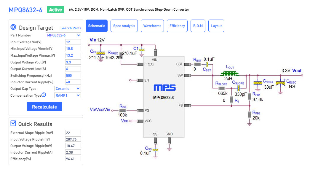
- Is it ok to follow the DC-DC designer tool values?
- How to calculate the feedback voltage? When I checked the datasheet its shown the equations to calculate using the Vref, Vramp voltages and resistor values, but I am little confused on the same. Please help here.
- Can I get the FAE email id, so that I can directly reach out to him in case any urgencies?
Below are my regulator requirements:
3.3V VR
Vin: 12V
Vout: 3.3V
Iout: <6A
1.8V VR
Vin: 5V
Vout: 1.8V
Iout: <6A
Thank you in advance.
Regards
Shyam
Hello Shyam,
I shall answer your questions in the order asked.
-
You should be fine with using the values as suggested by the DC/DC Designer Tool.
-
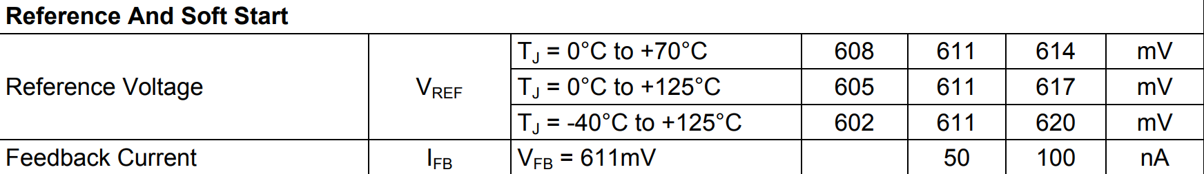
The feedback voltage of the MPQ8632-6 is around 611mV. In this datasheet, Vfb and Vref are used interchangeably, but this is not the same as Vramp. These thresholds vary in temperature, but this is the typical value as shown (following screenshot from page 9 of MPQ8632 datasheet):
-
For any urgent requests, please submit a ticket to the following link for direct FAE support: Contact MPS - Design Assistance Contact
If any other assistance is needed, feel free to also make a post on this forum.
Best,
Krishan
Hi Krishna,
Thank you for the reply.
Could you please help me to calculate the feedback voltage for the below DC -DC designer tool suggested design?
If I apply normal feed back voltage calculation (voltage divider equation) using Vout, RFB1, RFB2 then I am getting 0.561V only which is not matching with the 0.611V.
Regards
Shyam
You would need to make your calculations with respect to the fact that Vfb would typically be 611mV.
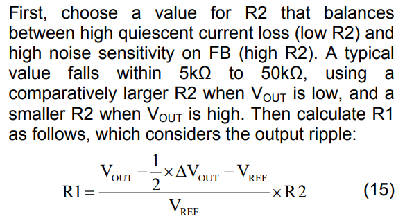
So for the feedback resistor ratio, formula, you can verify your feedback resistors by using the following formula:
So using this formula given the feedback resistors given by the DC/DC Designer tool:
R1 = [ (3.3V - 1/2(18.47mV) - 611mV) / (611mV) ] x 20kOhms
R1 = [ (3.3V - 9.235mV - 611mV) / (611mV) ] x 20kOhms
R1 = 87.7kOhms
I can see that if we substitute Vref = 0.5596V (which is close to what you calculated where Vref = 0.561V):
R1 = [ (3.3V - 1/2(18.47mV) - 0.5596V) / (0.5596V) ] x 20kOhms
R1 = [ (3.3V - 9.235mV - 0.5596V) / (0.5596V) ] x 20kOhms
R1 = 97.6kOhms, which then matches the DC/DC Designer, which I now see is the root to your question.
Do you have an evaluation board for this converter to verify this? Let me know.
Best,
Krishan
Hi Krishna,
Sorry, I am bit more confused now.
As per your first reply, the calculated R2 value is 87.7K and as per the second reply its 97.6K (DC-DC designer tool suggested this value).
Which resistor value i need to follow to make sure that the Vout is 3.3V?
Regards
Shyam
Hello again Shyam,
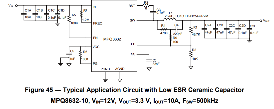
I can understand your confusion. In practice, Vfb = 0.611V with some tolerance above or below as shown in my initial post from the datasheet.
Please follow the schematic as shown in the following image, showing the typical application for when Vout = 3.3V.
Hi Krishna,
Thank you for the support.
I will implement the 3V3 based on your suggestion from the datasheet.
Also I am using other MPS solutions as well in my design to generate 5V, 1.05V, 1.8V, 1.2V. If I share the schematics pdf here, then Is it possible you to review the same? Or Do I need to send any separate email? Please let me know.
Regards
Shyam
Hello Shyam,
Thanks for letting me know about the other ICs you are covering for those 1.05V, 1.2V, 1.8V, and 5V rails. Please create separate posts for the schematics you would like me to review if you are comfortable posting them.
If you need more in depth review with a dedicated FAE to support the review of those schematics, please submit a ticket to the following link:
Contact MPS - Design Assistance Contact
Best,
Krishan