Hi,
According to the table on page 6 of the MPQ8623 datasheet, PGOOD low-level should be ~800 mV with a 10k pull-up to 3.3 V, and ~650 mV with a 100k pull-up to 3.3 V. However, looking at the figure 5 (page 16), the voltage is 800 mV when I_PG reaches 1.4 mA, which corresponds to about 2.4k pull-up to 3.3 V.
The disparity for 650 mV is even larger - 100k according to the table, 16.5k based on the graph.
What am I missing?
Thanks,
Milek
MPS writes kinda sloppy datasheets? They are spilling a lot of virtual ink on a mildly clever feature. The PG pin clamps low even when the IC is unpowered, but it isn’t a very strong clamp and they spill a lot of ink discussing it. So the curve ( probably taken off one preproduction sample) doesn’t match the datasheet value hopefully created with statistics on a sampling of units. How critical is this for you? Or are you just a very through kind of engineer?
It’s kind of important, because I am planning to use PGOOD for multiple concurrent goals in a very limited pcb area, and so I need to understand how much current I am dealing with in both clamped and non-clamped state.
Anyone from MPS care to comment? Could it be that the graph in figure 5 refers to the situation when the chip is powered on?
There is a line in characteristics showing Vpg at under 0.5V with Ipg at 10mA which is way better than the graph and I imagine indicates the PG pin characteristics when the chip is powered.
I find Eval boards quite helpful
@jshannon I understand that you are trying to be helpful and I really appreciate that. However, is there anyone from MPS support who can state with certainty what the graph in fig. 5 actually depicts?
It’d be great to obtain the answer without wasting a few weeks to get the eval/proto and then doing the experiments which won’t be statistically valid anyway.
Hi Milek,
Apologies for the delayed response.
Would you mind explaining what you are using the PG pin for? What are the multiple concurrent goals?
Best Regards,
Yu
Hi Yu,
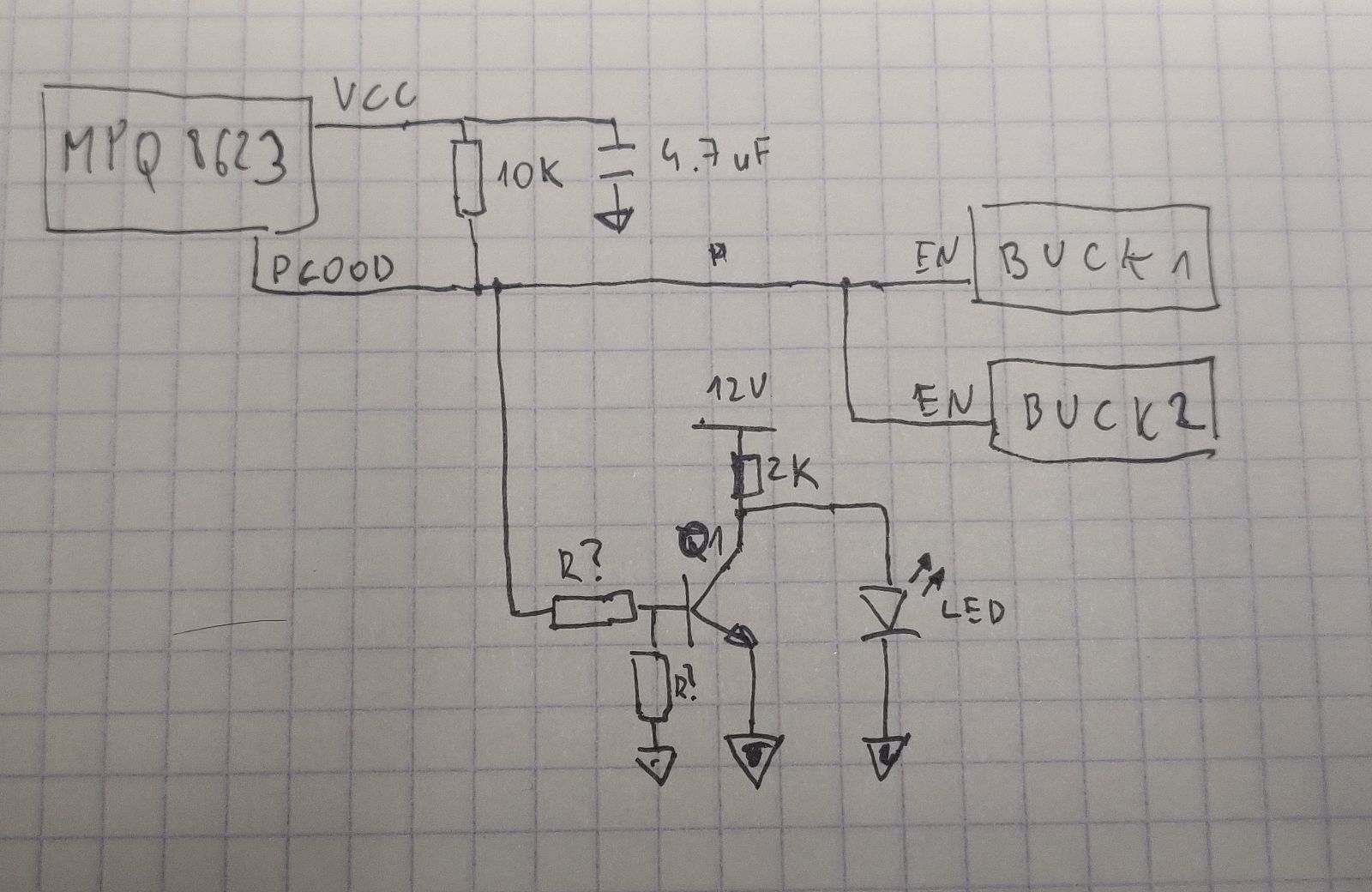
I want to control an LED and two other DC/DC bucks’ ENABLE inputs with MPQ8623 PGOOD signal. LED is in turn controlled by a transistor. Having conflicting information about how much current is available vs sunk in both modes of operation (powered and non-powered) makes it difficult to plan biasing for the transistor. I cannot go overboard pulling down, because the ENABLE inputs have relatively high ON levels (2.4 V), but if I don’t pull down strongly enough there is a risk of having too much current into transistor’s base even with low PGOOD.
I have extremely limited board space, where every 0402 component takes effort to squeeze in, hence I am looking for a minimal solution possible. And for that I need to know what I am working with.
Thanks,
Milek
Hi Milek,
Would you be able to share a snippet of the schematic for that pin? I would like to confirm my understanding of it.
Best Regards,
Yu
Hi Yu,
Here is the relevant part, please excuse my drawing skills. The (red) LED is supposed to turn off when PGOOD is HIGH. At the same time, both bucks should be enabled.
Thanks,
Milek
Hi Milek,
What is the current capability of the transistor base? What is the turn on threshold voltage of the transistor?
The PG graph is the I-V characteristic of the internal PG mosfet. This shows the current when applying voltage directly to the PG pin.
When PG is low, the PG internal mosfet will turn on and that relates to the PG graph. At this state, the max low PG voltage would be 1V with 10kohm pull up to 3.3Vcc. Depending on the on/off threshold of the transistor, the resistive divider is used to set the voltage at the base low enough for the transistor to be off and the LED would get pulled up and turn on.
When PG is high, the PG mosfet is off with small leakage current of around 3uA. PG will be pulled up to VCC and transistor turns on, driving the LED off.
Hope this helps.
Best Regards,
Yu