The datasheet does not seem to mention a maximum PWM frequency, though it is implied to be 200kHz from page 9. Am I safe to assume that a PWM frequency of up to 200kHz will allow 8A continuous / 12A peak?
Further, dead time requirements are not mentioned in the datasheet. Am I safe to assume that the IC takes care of dead time / prevents shoot through?
Lastly, could I request that these items be explicitly added to the datasheet?
Based on the graph on page 9, yes, it’s safe to assume that the maximum input PWM frequency to ensure the device operates within specs is 200kHz. Just as an FYI, based on the typical performance characteristics, the nominal switching frequency is 20kHz.
The IC does not have built in dead-time, so you will need to make sure there’s adequate dead-time based on your system requirements. The IC does have OCP that shuts down the FETs if short-circuit is detected, but it’s a priority to make sure your chosen dead-time is adequate via testing.
Thank you for the reply. Unfortunately I believe the dead time would be a function of the characteristics of the internal FETs you use in the IC, and it seems impossible to back calculate based on the datasheet provided.
Ie, even if no motor is connected, it could be possible for the high and low switches to allow current to pass from the power rail to ground.
Given that at 200khz a dead time of say 5ns would be fine, but a requirement of 500ns would impact the duty cycle beyond what I’d be comfortable with, I would really appreciate some more information here.
Passing the buck to the customer to test a Monolithic Power Systems design artefact does not fill me with confidence.
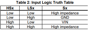
Thank you for your patience. After further research, the MPQ6541A indeed has capability of shoot-through protection. Whenever the LS and HS input is on at the same time, the switch node enters high-Z state:
That logic table is definitely supposed to prevent user error short circuit, however I don’t believe it necessarily follows that the internal FETs are protected from shoot-thru, due to the physical limitations of a FET?
If you are stating as a representative of MPS that designers do not need to worry about minimum dead time to prevent shoot through, that is great; could this information be documented in the datasheet please.
Is it possible if you can describe what scenarios you believe would cause both internal FETs to turn on? If the concern is about a possible shoot-through due to parasitic turn-on from aggressive switching of the switch node, then no need to worry about that because by internal FETs and gate resistance are already tuned by design to prevent that, and the IC should have passed that test via ATE before customer receives it.
If the concern is about having too small of a deadtime causing the HS and LS FET gates to overlap, then no worries there either. The IC designers have built in the IC logic that prevents both FETs from being on at the same time, which sort of simulates the deadtime. I realize my earlier reply saying that there’s no built-in deadtime may sound confusing now that I’m writing this paragraph, so I apologize for any confusion. Once again, this feature should also be tested via ATE and passed before any customer receives the IC.
Let me know if I can help clarify further. If you are seeing any sort of shoot through, let me know please so we can address it.
Our concern is because FETs are not ideal devices, and take a finite time to turn off, the chance can exist that a low side FET is still in the process of turning off when a high side FET turns on (or vice versa).
If the IC has logic preventing this, could I strongly suggest you add that information to your datasheet to make it really apparent? We were on the verge of selecting a motor driver from a different manufacturer because we could not be certain what was required from the existing datasheet. I would regard the existing input logic table as insufficient and ambiguous when it comes to shoot through protection, unfortunately.
To ease your mind, no we do not believe we have experienced such an event; we are hoping to avoid such a thing happening in the field.