Apologies for the late response; MPS had a company shutdown for the holidays.
The PWM frequency is limited by the device thermals. A quick way to figure this out would be to first calculate the expected IC power dissipation Pd (1) and then plug in Pd into the thermal equation (2)
(1) Expected IC power dissipation equation: Pd = Vreg x Qg x fsw, where Vreg is the gate driver voltage specified in datasheet, Qg is the FET’s total gate charge, and fsw is your frequency.
(2) Thermal equation: Tj_calc = (Pd x θJA) + Ta, where θJA = 40°C/W (from datasheet), and Ta is your system’s ambient temperature. The max Tj rating for the MPQ6528-AEC1 is 150°C, so if your calculated Pd from (1) results in Tj_calc in (2) being greater than 150°C, then your frequency is too high.
The device features over-current protection by sensing current via the low-side sense resistor. The internal low-side trigger threshold is typically 0.5V. It also features short-circuit protection by sensing the FET Vds via Rds(on). The internal short-circuit trigger threshold is set by the OC_REF pin.
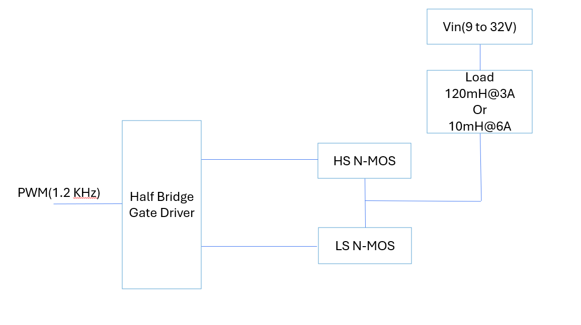
Yes, a single PWM drives both high-side and low-side for its respective phase.
We have some other queries about this part can you please check
Our requirements are as below
Continuous load current (RMS): 6A @24V battery system
Operating temperature: -40°C to +85°C
Operating voltage: 9V to 32V
Jump start: 36V
Input PWM: 1.2kHz
Duty cycle: 100%
Load dump: 65V for 400ms
No. of loads: Inductive 120mH connected to vin
2-layer PCB
Current sense monitoring and overcurrent protection (without microcontroller or software intervention)
Overvoltage/ Short circuit/ Shoot-through protection- Both HS and LS need to be protected
Auto-restart in case of thermal shutdown (without microcontroller or software intervention)
Fully RoHS compliance without any exemption (lead content <0.1%)
As we see in datasheet there is VDS monitoring for short circuit protection and shunt resistor sensing for over current protection. Can we use single configuration of VDS sense for both over current protection and short circuit protection by setting OCREF pin threshold to 0.5V.
2)Is there any protection for shoot through at IC side because in datasheet only dead time adjustment option given. If any case that dead time requirement is not meeting, then how IC will protect that fault.
3)Can you please suggest any external NMOS for our application which should be ROHS compliant
For 6A load what should be OCREF threshold need to set
For your reference I am attaching the application diagram
Apologies for the delay in response. Your load dump requirement of 65V exceeds the absolute max spec of the MPQ6528. I would recommend adding a TVS diode to clamp excess voltage.
Regarding your other questions:
Overcurrent protection (OCP) is sensed by measuring the voltage drop from drain current and Rsense on the low-side. Short-circuit protection (SCP) is sensed by measuring the voltage drop from drain current and Rds(on). Setting OC_REF = 0.5V would not result in single configuration.
The OCP/SCP should turn off the IC if shoot-through happens, but I recommend setting deadtime with adequate headroom.
I recommend selecting an NMOS FET with at least 1.5X voltage and current rating for your application for adequate headroom (if the FET is damaged, then 99% of the time the driver will get damaged as well). Since your load dump is 65V, then I recommend going for at least a 100V FET. Ensure the FET has low Rds(on) and total gate charge to limit conduction and switching losses.
OC_REF threshold is dependent on the Rds(on) of the FET you select. For example, if you want OCP to trigger at 8A and your FET has Rds(on) = 50mOhm, then you should set your OCP_REF = 8A * 50mOhm = 0.4V
Thank you for your patience. Yes, that is the equation for power dissipation, and yes, you can use the same FET for HS and LS, but keep in mind that the equation needs to account for 4xQg since there will be 4 FETs for H-bridge topology.
The datasheet specifies JEDEC JESD51-7, which is tested for 2oz copper on the outer layers of a 4-layer PCB.