We are planning to use MPQ5850 EVM, for unidirectional power supply.
I have below question:
I am providing a Pulsed supply of 11.3V with 200Hz frequency at VIN of EVQ5850 and sinking 400mA at VOUT during the TON (connected Vout to a resistive load).
But due to capacitor at Drain pin which is (4.7uF + 470 uF), the output voltage during TOFF was also 11.3V. I experimented by removing capacitors, output goes to zero during TOFF but i am unable to sink any current at output during TON.
What is minimum capacitor value that can be placed at output, such that output voltage goes to zero during TOFF and i would be able to sink current during TON.
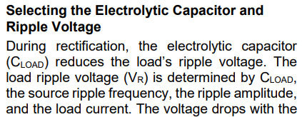
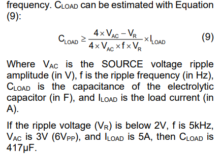
However, here is also the following considerations you should take into account regarding min ripple specs in conjunction with minimizing the sizing this capacitor (pages 24,25):
Thanks for response. As mentioned above we are providing pulsed DC voltage with frequency of 200 Hz.
We are expecting output signal(voltage & current) to be in synchronization with input of EVM. When we test with Cload of 4.7uF, we still see voltage is retained at output during Toff.
Is there any capacitor value we could test with such that output voltage goes to 0 during Toff and part will still be able to supply current during TON.
You’ll need to keep the minimum capacitance of 4.7uF as the MPQ5850 needs this as a bleeder / active discharge that is only on when Vin is low. Be sure that this capacitor is a low-ESR ceramic capacitor right at the DRAIN pin.
Perhaps adding an NMOS-based discharge tied to EN / Vin to achieve what you are trying to do. You could place this between the DRAIN pin and GND so it turns ON during TOFF and OFF during TON. This would be quick and minimize loss as it would happen only when needed.
Alternatively, a simpler solution would be adding a bleeder resistor. You would need to size this such that the capacitor falls to your target between pulses. However, this would be more lossy than the last suggestion I made.
Let me know if things have changed / how testing goes.
Thanks for response, just by removing C4(470uF) i was able to get rid of power during toff.
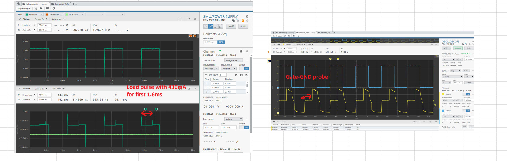
But when we tired providing 200Hz of voltage pulse to Vin of EVQ5850EVM by connecting 25 ohm at load, we see there is full conduction(~460mA) only after 1.6ms, but until then there is drop of 30mA. We probed the gate signal and see that also has transition after 1.6ms. Below i have attached both screenshots for reference.
Ideally MOSFET would be conducting fast but we see there is delay, could this be improved or is this how EVM is expected to work.
I am looking into this issue. I will get back to you when I have a suggestion from this point. Thank you for your patience and apologies for the delay.
In short, nothing is wrong with the EVM here. The MPQ5850 is delaying the gate drive until it’s internal supply threshold or current state limit is satisfied. Your measurement method and the caps in place result in the 1.6ms delay that you see.
When VIN is pulsed the MPQ5850 must charge the internal controls and pass EN and protection thresholds before it can drive the external FET.
Removing the 470uF previously seems to have affected how fast VCC and the internal bootstraps charge on each VIN pulse. If VIN rises slowly, then the IC can’t immediately drive the full gate current. Inrush detection may also limit conduction until things have passed as well.
When you made measurements, did you use a ground spring or a differential probe? There are jagged peaks that could be a symptom of ground clipping from probing. Just want to ensure that can be narrowed down.