Hi,
I’m using the MPQ5031GRE-0001-AEC1-Z in a USB PD board, and I was wondering what I can change via I2C, and what I can’t change based on the OTP which MPS programs themselves.
I would like to be able to change two things from the default configuration of the MPQ5031GRE-0001:
- I would like to be able to change the GPIO pin functions.
- I would like to be able to change the default current limit.
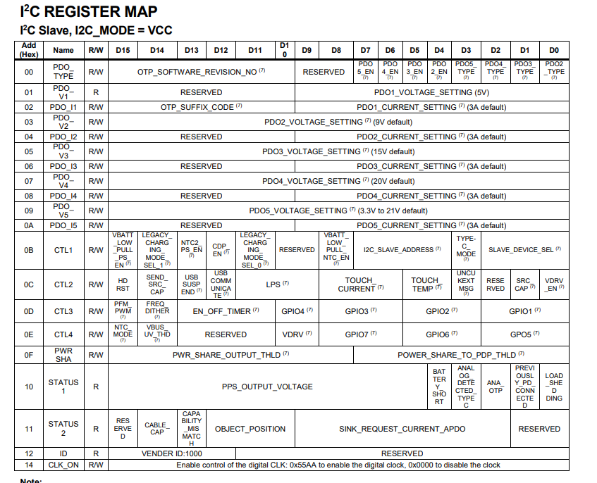
I can’t figure out what the configuration code “0001” (which is the identifier for the register setting stored in the OTP) refers to. I thought it pointed to PDO2-5 types, as they are have the value 0b, 0b, 0b, 1b (page 42), but the configuration code can take on values from 0-F.
The table underneath the PDO items is also listed as OTP items, and it includes thing like GPIO and power threshold. Does that mean that I need to find another variation of the IC to configure it the way I want to? If so, how do I tell which variation will carry the functions that I’d like to add to the board.
Could someone explain to me which values I can change from I2C, which ones come with the OTP, and what the configuration code actually refers to?
Thanks!