Dear Team,
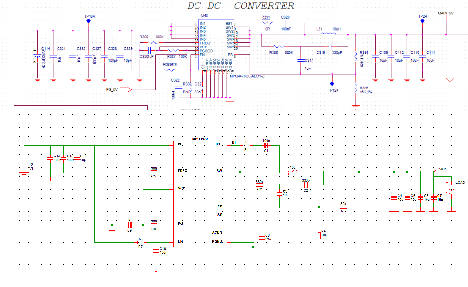
I am new to SIMPLIS, simulating this MPQ4470
My input is 12V and the required output is 5V,load will take maximum current of 3A.
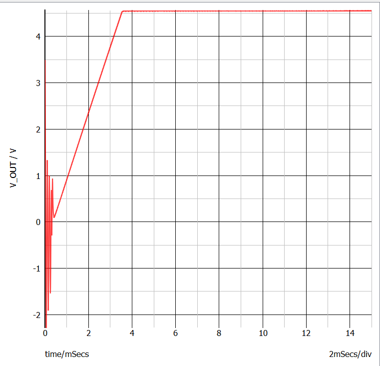
My output is clamped at 4.5V not coming to 5V.
May I know where I went wrong
Dear Team,
I am new to SIMPLIS, simulating this MPQ4470
My input is 12V and the required output is 5V,load will take maximum current of 3A.
My output is clamped at 4.5V not coming to 5V.
May I know where I went wrong
Hi HARI,
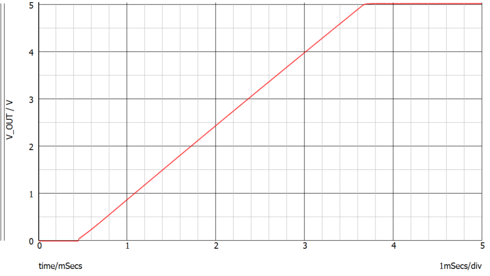
Suggest using equation 18 and 11 to set RFT because R1, C3 external voltage ramp affects the output. Here is a capture using 92kohm for RFT.
Best Regards,
Yu
Hi Yu,
Thank you for your time.
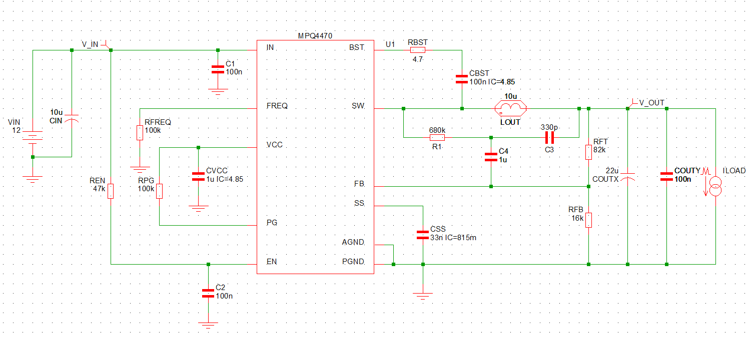
Below image shows the circuit diagram which is present in our real board and it is giving 5V output.
Regards
HARI
Dear HARI,
I had tested couples of MPQ4470.
I can only say that the input vs output is completely abnormal at my case.
Case 1:
Vout=12V, Vin=26-30V
The output is not even regulating properly at 0A to 5A range.
The output will variate almost over >1V.
I am not sure this is a bug or what when you use DCDC Design Tool.
The suggested loop and feedback passive components not even converge on MPQ4470.
This mean the MPQ4470 cannot output the required output voltage.
I am completely loss on this buck converter.
I had used a lot of MPS product and once I see that T shape of compensation converter
I will immediate drop this selection.
MPS is not responding to all this issue and I don’t understand why.
Even when using MPS simulator the suggested value cannot converge as well.
Well you are not ALONE.
Hi Hari and Brian,
Sincere apologies for the delay here.
The simulation is a tool you can use to help design, however, it is best to verify through testing on an evaluation board.
If you experience issues with the simulation and would like further support, you can reach out to MPS NOW Remote Support - Support.
Best Regards,
Yu
Of cause I had also reached this service but no response are given.
So what do you expect me to take more action.
I doubt that my computation follow MPS documents are faulty.
So if there are any design constraints that need to be included during design please tell us.
Meanwhile, we are losing patient. If there are no solution on 12V MP(Q)4470 stable design we had to give up and select other company converter. Stability is what we concern here. COT itself is poor on line and load regulation during PSM and CCM so trade off already been given but with such so poor line and load regulation on CCM this is completely unacceptable.
Bests,
Brian
Hi Brian,
We are actively looking into why you have not received a response to help assist and resolve your questions.
In terms of solutions, if the line and load regulation for this part does not meet your requirements, we do have other solutions such as MPQ4341 with tighter regulation that you can check out.
MPQ4341-AEC1 | 36V, 5A, Ultra-Low Quiescent Current, Synchronous Step-Down Converter with Multi-Phase Capability, AEC-Q100 Qualified | MPS (monolithicpower.com)
This part does utilize ZDP control which is unique to MPS. You can refer to the application note below.
Zero-Delay Pulse-Width Modulation Control (ZDPTM) | Application Note | MPS (monolithicpower.com)
Best Regards,
Yu
I think MPS internal have different departments that are not sharing information between depar,
Fox is handling the issue and still not resolving the design issue.
I believe that MP(Q)4470 itself is over 5 years but COT itself is not the most common buck converter like current-mode or voltage-mode. And COT itself is more happy to use high ESR output capacitor.
But good, gernal and morden bulk capacitor is having low ESR that making external ramp is a must.
So I don’t think when using high ESR old capacitor is the way.
As a result MP(Q)4470 COT buck converter documents need to improve when dealing with 5V above output voltage.
I am sure 5V or below output is stable and good because I had successfully run aged test.
Bests,
Brian
The RC over the inductor can generate any level of ramp you want. High ESR output cap is not the way to go as that gives high output voltage ripple.
Nope the theory said if you do had studied the MPS COT document.
High output ripple actually helps to stable the system. Which you might thing this is unbelievable.
The reason of external ramp is because of stability due to overall loop gain aka phase and gain margin.
When the output cap esr is high there are no issue on the feedback and only voltage divider is needed.
Once the esr is low enough and introduce stability issue external ramp is to compensate the problem.
This is why COT is good at using large bulk capacitor.
But most cases are MLCC these days so COT with external ramp is a must.
Bests,
Brian
I think we are saying the same thing
Cannot tell you are directing to the same idea.
You are proposing high ESR is not the way by truth is that to resolve the issue lazily.
Bulk capacitor is what you need, however the only issue is lifespan efficiency and heat up.
Meantime, if you are trying to help why not propose a workable ramp and configurations?
Otherwise I cannot see any points that you do trying to help.
No data no schematic nothing are given out.
Regards,
Brian