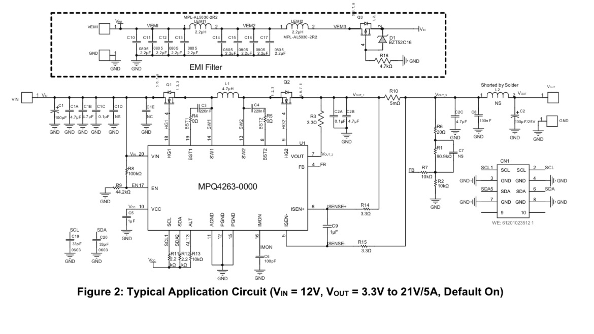
I have replicated the above schematic using MPQ4263GQVE-0002-AEC1 part number, and I am unable to see any output when I’m operating with same input voltage range provided in the datasheet. Could you kindly clarify if MPQ4263 0002 variant warrants a compulsory I2C configuration to see expected output. If so, what are the parameters that has to be configured through I2C (ie., VOUT, Frequency, EN etc)
Although the EN pin is held at 3.6 V in the above schematic, the datasheet link below on page 29 of MPQ4263 document states that the output is controlled by the operation command bit and must be set to enable the output on/off.
Thank you for posting your question in the MPS Technical Forum.
The MPQ4263-0002 defaults the OPERATION Register (01h) as ‘0’ (OFF).
Therefore, you will need to toggle this register value to ON via I2C.
Also, the switching frequency is preset to 280kHz, and the output voltage to 5V.
I am attempting to implement current limiting using the register configurations specified in the MPQ4263 datasheet. As mentioned in the datasheet, the current-limit function is expected to operate only in Forced PWM mode. However, during testing, the expected current-limiting behavior is not observed in either Auto PWM or Forced PWM modes.
Test Setup and Configuration:
VOUT set to 5 V with a DC electronic load connected
Current-limit threshold configured to 0.7 A
LDC disabled
CC enabled with CC blanking timer set to 3 ms
Operating modes tested: Auto PWM and Forced PWM
Sense resistor value: 5 mΩ
Observed Behavior:
Load current exceeds the programmed current limit, suggesting that CC mode may not be engaging
IMON pin remains at 0 V even when the load is drawing significant current
Could you please advise on the recommended next steps to debug or validate the current-limit functionality, or let us know if there are any additional configuration requirements or checks we should perform.