I need to design a USBC-PD (source only) and the MPQ4242 is one of the short listed devices. On the datasheet, I noted three different codes, MPQ4242GVE-0000-AEC1-Z, MPQ4242GVE-0001-AEC1-Z, and the MPQ4242GVE-0015-AEC1-Z. The explanation for the MPQ4242GVE-0015-AEC1-Z part is missing. What does this option stand for?
As a general question, which one of these devices (if any), can be used for a USBC-PD (source only) out of the box without the need for configuration?
The "-xxxx’ is the custom config codes assigned on customers request. It consist of unique OTP register map as per the customer needs. If for your application, a custom config code is needed please reach out to us here: MPS NOW Technical Support form: MPS NOW Technical Support - Contact and one of the team member can work with you in creating one.
Yes, MPQ4242GVE-xxxx can work for USB C-PD source.
Thank you for your reply. I understand that the MPQ4242GVE-xxxx can work for USB C-PD source. But can it work without the need to apply configurations (so with default values)? If so, what are the default configurations of this device.
The default code is provided in the DS on Pg. 56. If the defaults don’t work for your application, you can “configure” the part as per the your requirements but it would go back to the default once power cycled.
Hi,
can an I2C EPPROM be added so that configured register values can be saved in the EEPROM and read out at every power up cycle?
If I understood well, the USB-to-I2C adapter provided with EVAL Kit is only to play with the IC for different configurations, but the configuration must be loaded/flashed every time after power up cycle, right? For example the GPIO1 has the defult function POWER_SHARE1 and if we want to use this pin as Device_Detect_Pin in order to detect when the usb-c cable is attached, the special IC order form factory is needed where this pin will be factory preprogrammed to ATTACH_FLT_ALT function, correct?
If we want custom configuration that works at each power up cycle we need to order pre-programed IC form factory, right? Alternative solution is to adda external uC that will change configuration ant each power up cycle, right?
We got the data sheet rev 1.0 9/11/2024 of the new chip revision, MPQ4242B. There is a Note on the page 3 “The MPQ4242BGVE-0000-AEC1 is the default 60W PD version, which can be configured once by the onetime programmable (OTP) memory. Other suffix codes cannot be written with the OTP again.”
However, on the page 56 the OTW1_PDP is still 45W (default).
Hi,
can an I2C EPPROM be added so that configured register values can be saved in the EEPROM and read out at power up?
If I understood well, the USB-to-I2C adapter provided with EVAL Kit is only to play with the IC for different configurations, but the configuration must be loaded/flashed every time after power up cycle, right? For example the GPIO1 has the defult function POWER_SHARE1 and if we want to use this pin as Device_Detect_Pin in order to detect when the usb-c cable is attached, the special order form factory is needed where this pin will be factory preprogrammed to ATTACH_FLT_ALT function, correct?
If we want custom configuration that works at each power up cycle we need to order preprogramed IC form factory, right?
We got the data sheet rev 1.0 9/11/2024 of the new chip revision, MPQ4242B. There is a Note on the page 3 “**** The MPQ4242BGVE-0000-AEC1 is the default 60W PD version, which can be configured once by the onetime* programmable (OTP) memory. Other suffix codes cannot be written with the OTP again.”
However, on the page 56 the OTW1_PDP is still 45W (default).
Does a reference desing example with the externall EEPROM exist from your side and what are min. requirements for EEPROM chip?
According to the data sheet MPQ4242 features an I2C Slave interface. Therefore just attaching an EEPROM on I2C lines will not work. The external uC is needed here, right?
Regarding the chip programing, this can be done only in the MPS factory. It means, all statements from data sheet like:
“For the default IC, line drop compensation is disabled in PPS mode. Line drop compensation can be enabled in PPS mode through factory OTP trimming.”
Line drop compensation can be configured via the I2C or OTP. The compensated voltage is the
same for all voltages.
*The peak current limit can be configured via the I2C or one-time programmable
(OTP) memory.
*** The MPQ4242BGVE-0000-AEC1 is the default 60W PD version, which can be configured once by the onetime programmable (OTP) memory.
are related to the chip programing in the MPS factory. The End-User can’t do this, right?
How much does it take to get samples that are preprogramed to desired configuration?
I would like to discuss more details about system we want to design, but share details here in forum is not an option.
How can we get direct support form FAE per email? (I have already sent support request through the MPS NOW Technical Support Contact Form, but no response for now)
just a comment on differences between MPQ424 and MPQ424B for max default power delivery, 45W vs. 60W.
The MPQ4242B revision is delivered with 60W standard configurration.
Which Register in the OTP default register settings is the 60W configuration related to?
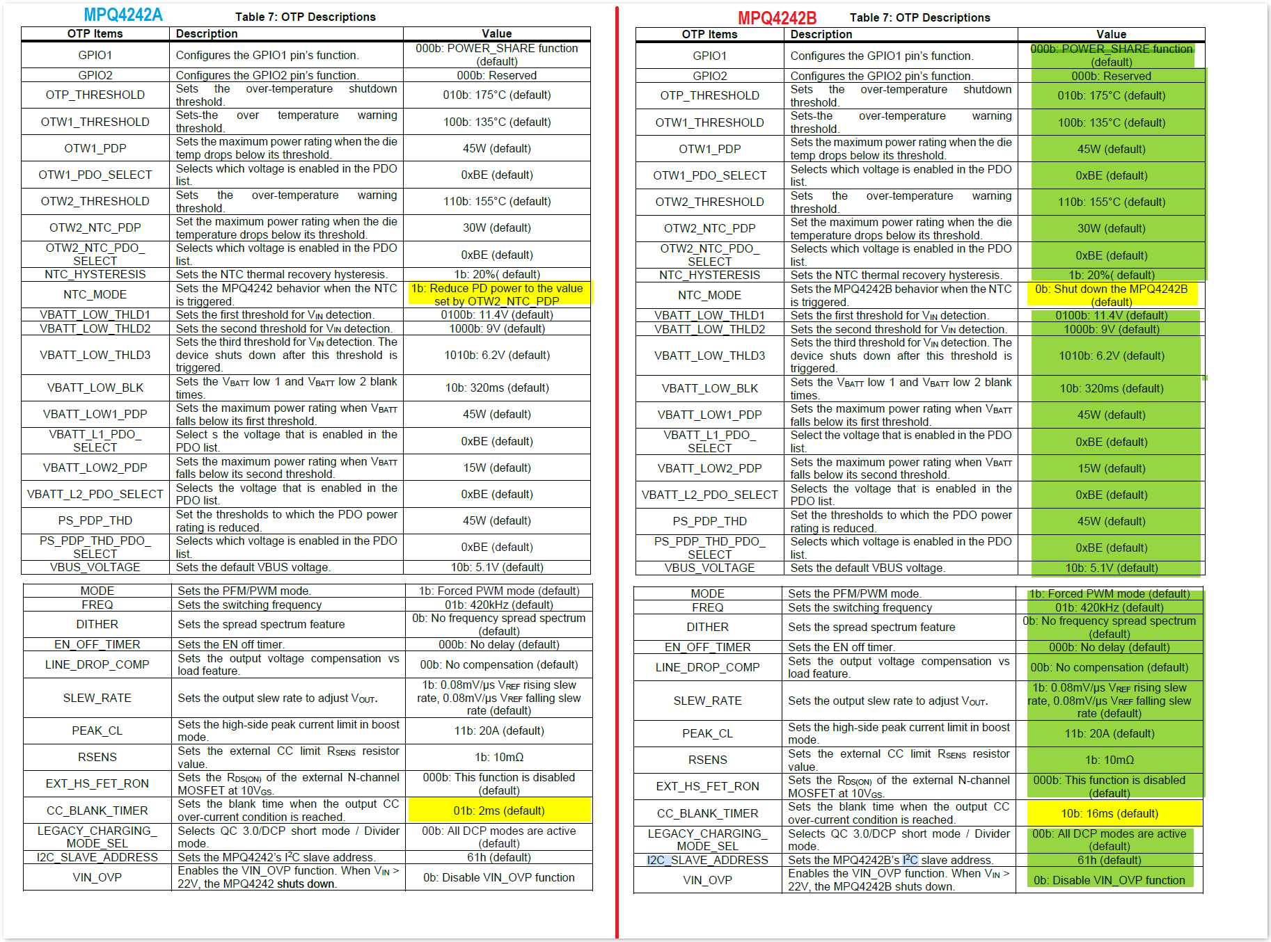
I’ve compared OTP register settings from both data sheets and found only different seeting for these two registers:
MPQ4242 NTC MODE: 1b: Reduce PD power to the value set by OTW2_NTC_PDP
MPQ424B NTC MODE: 0b: Shut down the MPQ4242B (default)
I do not believe we have a reference design for implementing this. I believe that an external device like an mcu is needed since it would have to read contents from EEPROM and write to device.
Could you explain the functionality you are trying to achieve? It would help be better determine if this part could be used or if it would require something else.
I just want to understand how the configuration concept and OTP work.
If we order the 0000 version of the chip, can we change the default function of the GPIO1 pin from POWER_SHARE to the ATTACH_FLT_ALT function using the EVKT-USBI2C-02? Will this change be non-volatile so that GPIO1 is going to have ATTACH_FLT_ALT function after power cycling?