Dear MPS Support Team,
We are currently using the MPQ4242BGVE-0017 model from MPS, and we are trying to use the OTW1, OTW2, and NTC functions.
Goal:

Register Configuration:
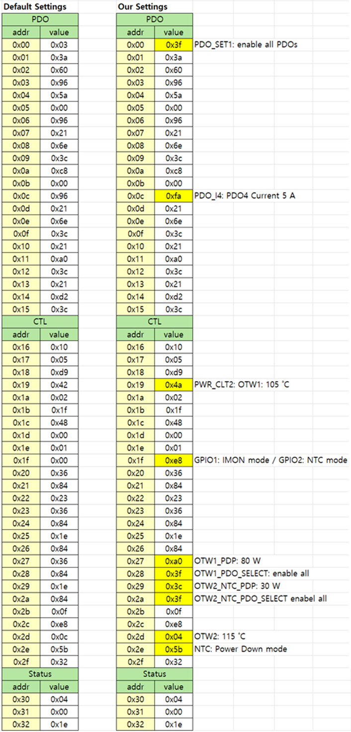
| Our Settings | ||||
|---|---|---|---|---|
| PDO | ||||
| addr | value | |||
| 0x00 | 0x3f | PDO_SET1: enable all PDOs | ||
| 0x01 | 0x3a | |||
| 0x02 | 0x60 | |||
| 0x03 | 0x96 | |||
| 0x04 | 0x5a | |||
| 0x05 | 0x00 | |||
| 0x06 | 0x96 | |||
| 0x07 | 0x21 | |||
| 0x08 | 0x6e | |||
| 0x09 | 0x3c | |||
| 0x0a | 0xc8 | |||
| 0x0b | 0x00 | |||
| 0x0c | 0xfa | PDO_I4: PDO4 Current 5 A | ||
| 0x0d | 0x21 | |||
| 0x0e | 0x6e | |||
| 0x0f | 0x3c | |||
| 0x10 | 0x21 | |||
| 0x11 | 0xa0 | |||
| 0x12 | 0x3c | |||
| 0x13 | 0x21 | |||
| 0x14 | 0xd2 | |||
| 0x15 | 0x3c | |||
| CTL | ||||
| addr | value | |||
| 0x16 | 0x10 | |||
| 0x17 | 0x05 | |||
| 0x18 | 0xd9 | |||
| 0x19 | 0x4a | PWR_CLT2: OTW1: 105 ˚C | ||
| 0x1a | 0x02 | |||
| 0x1b | 0x1f | |||
| 0x1c | 0x48 | |||
| 0x1d | 0x00 | |||
| 0x1e | 0x01 | |||
| 0x1f | 0xe8 | GPIO1: IMON mode / GPIO2: NTC mode | ||
| 0x20 | 0x36 | |||
| 0x21 | 0x84 | |||
| 0x22 | 0x23 | |||
| 0x23 | 0x36 | |||
| 0x24 | 0x84 | |||
| 0x25 | 0x1e | |||
| 0x26 | 0x84 | |||
| 0x27 | 0xa0 | OTW1_PDP: 80 W | ||
| 0x28 | 0x3f | OTW1_PDO_SELECT: enable all | ||
| 0x29 | 0x3c | OTW2_NTC_PDP: 30 W | ||
| 0x2a | 0x3f | OTW2_NTC_PDO_SELECT enabel all | ||
| 0x2b | 0x0f | |||
| 0x2c | 0xe8 | |||
| 0x2d | 0x04 | OTW2: 115 ˚C | ||
| 0x2e | 0x5b | NTC: Power Down mode | ||
| 0x2f | 0x32 | |||
| Status | ||||
| addr | value | |||
| 0x30 | 0x04 | |||
| 0x31 | 0x00 | |||
| 0x32 | 0x1e |
The Results from our testing:
1. OTW1 Behavior
We set the maximum output power of PDO4 to 100 W (PDO4: 20 V / 5 A), and then tested by changing the OTW1 maximum power (OTW1_PDP, 0x27) to 80 W and 60 W.
-
When OTW1_PDP is set to 80 W, we confirmed that once OTW1 is triggered, the MPQ4242 controls the power to the specified maximum level (80 W). (PDO 3, max power 80 W was selected.)
-
However, when OTW1_PDP is set to 60 W, OTW1 triggering causes the system to repeatedly loop through the following sequence:
(20 → 40 → 60 → charging stops → 20 → 40 → 60 → charging stops → …)
Could you explain the reason for this behavior?
2. OTW2 Behavior
We found that even when OTW2 occurs, the output is not controlled according to the maximum power value configured for OTW2 (OTW2_NTC_PDP, 0x29).
-
Although the OTW2 Status bit is set, the power does not change to the configured OTW2 limit (30 W).
-
We tested two conditions:
(1) OTW1 enabled and OTW2 enabled
(2) OTW1 disabled, OTW2 enabled only
In both cases, althought the OTW2 Status bit was set, the MPQ4242 did not change the power to the OTW2 maximum setting. -
In our register configuration, only the following settings were changed for OTW2:
OTW2_NTC_PDP (0x29) → 0x3C
OTW2_NTC_PDO_SELECT (0x2A) → 0x3F
Is there any incorrect configuration in these settings?
3. NTC Shutdown Mode
We would like to confirm the expected system behavior when NTC shutdown mode occurs.
-
When NTC shutdown is triggered, we observed that all MPQ4242 status register values stop updating. Is this the correct and intended behavior?
-
Should VBUS charging be completely disabled by the MPQ4242 when NTC shutdown occurs?
-
Is there any possibility that the MPQ4242 chip may be damaged when NTC shutdown mode is activated?
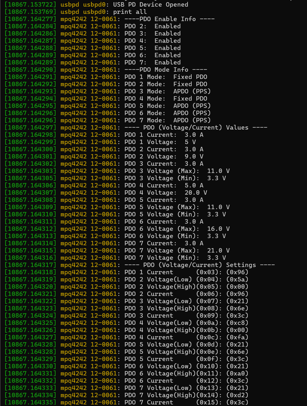
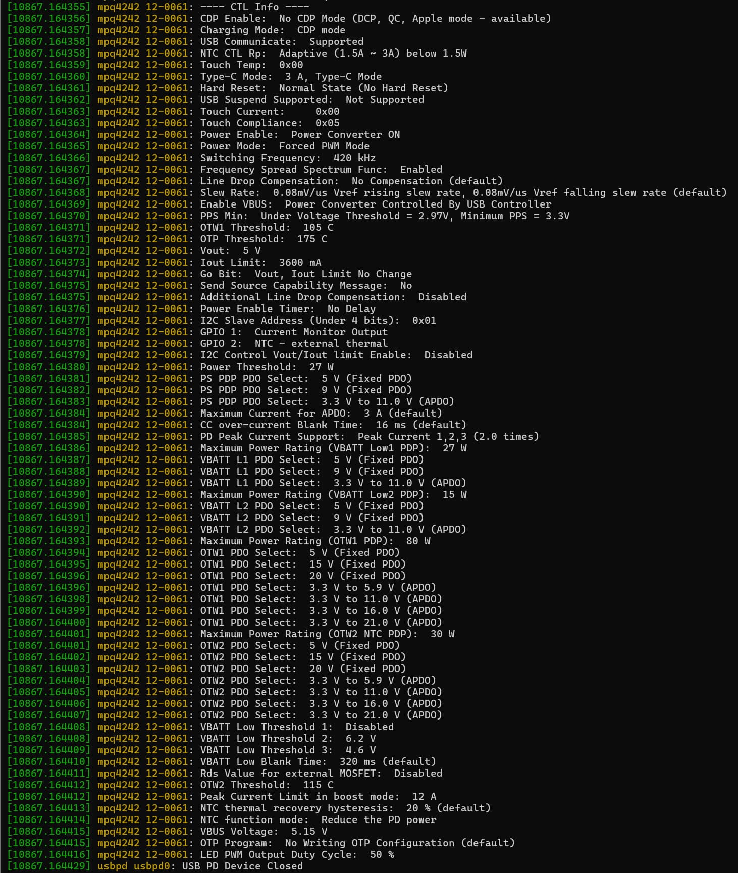
The Register bit field information for our settings is shown below, captured with no USB-PD connection:
We have a substantial number of MPQ4242 chips and want to ensure that we are using them correctly, and we would appreciate your support in resolving the issues we have observed.
Could you please review our register settings and usage scenarios to confirm whether there are any misconfigurations or incorrect operational assumptions?
Thank you.