We developed a prototype with the MPQ4242, whose charging section is largely based off of its EVQ4242 evaluation board. I2C functions work, and activity can be seen on the CC and USB data lines, but charging power never seems to turn on. This is true whether using our own chip settings, or those from the eval board. The cabling and loads I’m using work with the eval board. I do not measure any unexpected shorts between pins, and soldered contacts appear good.
I checked the current sensing resistor on our board and confirmed it was soldered down OK, and measured the expected range. Removing it, I measured about 4 mega-ohms resistance between ground going to the USB-C jack, and main digital ground around the MPQ4242. Looks like the chip should be able to monitor charging currents.
When I just plug a micro-USB to USB-C cable in, no host data connection on D+/D-, I see a 17msec long pulse at 3.4 volts on CC2, which then drops and stays at zero afterwards. I see similar on CC1, but only reaching about 1.8 volts. I can see some bursts of pulses on CC1 when I kill power to the board, followed by a single large pulse after that. So it seems like some activity is coming out of the MPQ4242.
When 24V power is fed to the chip, only the cable plugged in, I see about 570 mV on VBUS. When I disconnect 24V power to the board, about 5 seconds later I see 5 volts jump up on VBUS before gradually decaying.
Appreciate any suggestions you have on other things to check!
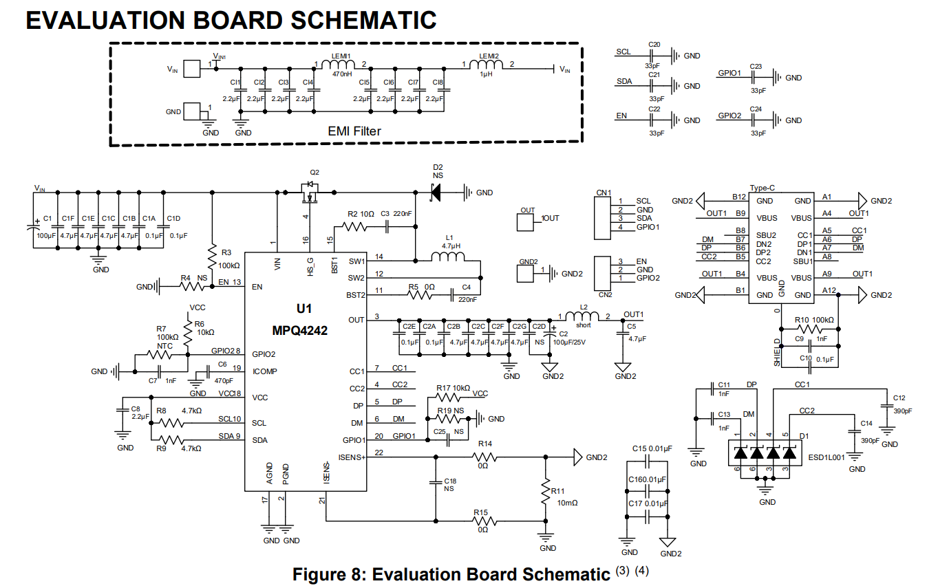
This is certainly some unusual behavior. Upon an initial look to start somewhere for debugging, it would be best to start at the input in this case. I noticed that your EN pin was tied directly to “+5V MPS Rear”. The typical current for this pin is on 6uA. This would be a good place to limit the current.
Also in the typical applications, VCC is not externally connected to anything as it is an output internally generated by Vin, so it only needs to be decoupled to GND using a 2.2uF capacitor and not connected to “+5V MPS Rear”.
Refer to Figure 8 for the following notes on VCC and EN this subject:
Thank you very much for the response, Krishan!
It appears some of the parts we had sourced for our first prototypes are a variant which stops charging if Vin goes above 20 volts. The evaluation board and samples we received from MPS did not have this limitation. Our design is using 24V power, so the 20V limit was a problem. I had run the charger off 12V previously, but that was when our 3V3 supply was also connected to Vcc of the MPQ4242, making things unhappy.
Our prototype is charging now once we replaced the MPQ4242 with samples from MPS. Saurabh Shah (MPS) is looking into how we might be able to force that “over-voltage protection” (OVP) option off. It’s not listed in the editable parameters in Virtual Bench Pro.
I am glad that Saurabh is helping you find a way to bypass the OVP setting and allowing for your design to operate at 24V and still having the ability to charge. Perhaps he can help you set the OVP threshold above 24V such that you still have voltage protection measures.
Saurabh responded that OVP setting is not configurable, at least in the field, by us.
The -0001 variant is mentioned in the data sheet as having a 20V limit, but we actually bought a -0015 from Mouser. Unfortunately, no advance info was available on that version, and I didn’t realize some of the register settings could not be overwritten via I2C, even at runtime.
I see. If you do disable OVP for this application and externally enable measures that would act as OVP. I would suggest a voltage protection switch if you do proceed to proceed to disable OVP if you foresee this behavior for your application.