Hello,
I am trying to operate the MPQ4210 evalution board in parallel operation. Can this be possible using this MPQ4210 board. If yes please help me in this.
Thanks and Regards
Hi Kranthi,
I believe our engineer in Europe was working with you on this part and the operation mode. Were her recommendations not working?
No one is helping me from Europe. Just three days back I got an update from MPS that they updated the Virtual bench software, I did get output voltage from the evaluation board. Now I just want to know whether they can be paralleled or not. There is one more customer of MPS also trying to connect in parallel he even asked same question but no one replied.
Just now one of your employee from Germany, told me parallel operation is not possible that he did not find much information regarding the current sharing.
Hi Kranthi,
Please continue to be in email contact with our German office as the time difference between you and I will create delayed answers on my part, however, I can still assist. The current sharing issue that he mentions refers to that one device needs to be a master and the other a follower to prevent steady state stability issues. In a transient response situation, it is possible that one device goes into OCP before the other and that would drop the output temporarily. This device is missing a synch input pin that would be typically be used to be out of phase with the other converter’s clock.
so now how to implement the parallel connection.
I had one more doubt that the output of this MPQ4210 is I2C programmable. When battery is connected to the output terminals of the converter board is it possible to control it with a PWM using Microcontroller.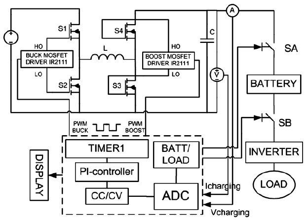
The uploaded figure controlling output using MCU. It was my part of the project to design a control system using Microcontroller.
Hi Kranthi,
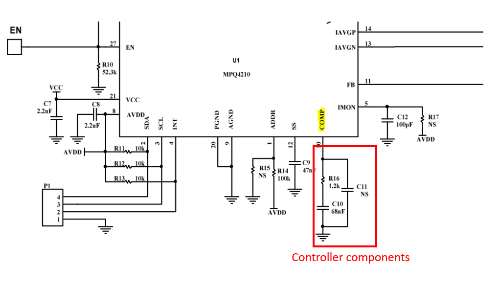
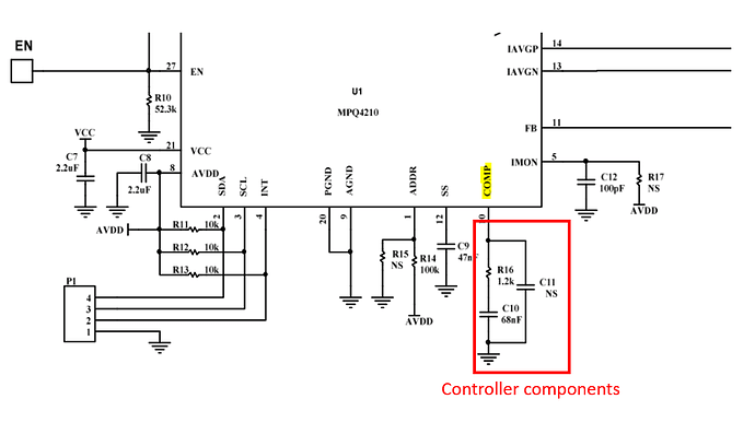
On your own caution if you want to proceed with the parallel connection, you will have to have each device with their own individual I2C addresses and use the common COMP pin connection as shown below (connect all COMP pins together). For example, if you have 3 evaluation boards, you must keep one of them with the controller components and connect the 3 boards using the COMP pin.
Please be aware of powering it up and monitor the output and SW nodes.
You may also change the output voltage by setting the REF bits (Vout=10*VREF) and then write GO_BIT=1.
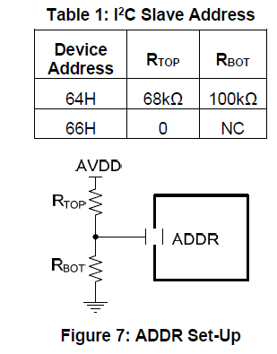
So, the I2C address of MPQ4210 is 66 how can we get different I2C addresses for same MPQ4210 boards.
You told me to connect the boards using COMP pin. How can I do this where can I find this pin on the Evaluation board. I can set teh output voltage using Virtual bench.
I sent a control design figure to you using Microcontroller. Can that be possible.
Hi Kranthi,
Please refer to Figure 7 in the datasheet of MPQ4210:
Pin 10 is the COMP pin and you may need to solder down a wire to both boards. You can pull from the node that connects C11 and R16:
Hello, This is more information than MPS have given me on paralleling two converters. Have you tried their suggestion to common-up the COMP pins?
It would good if MPS would explain the principle behind their suggestion.