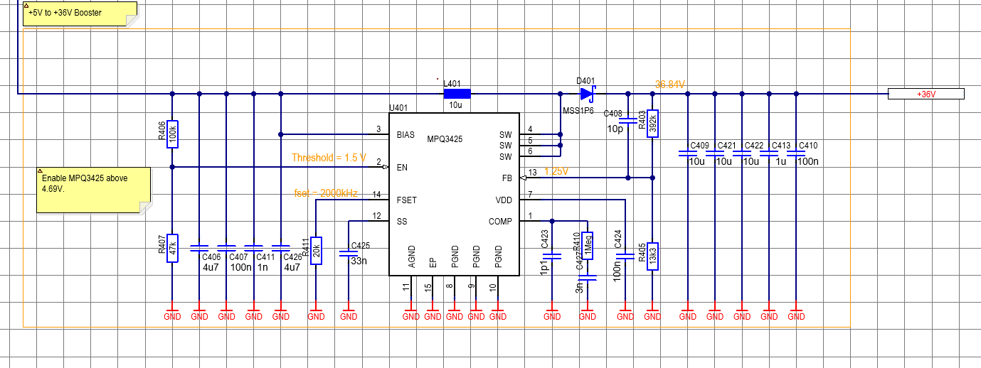
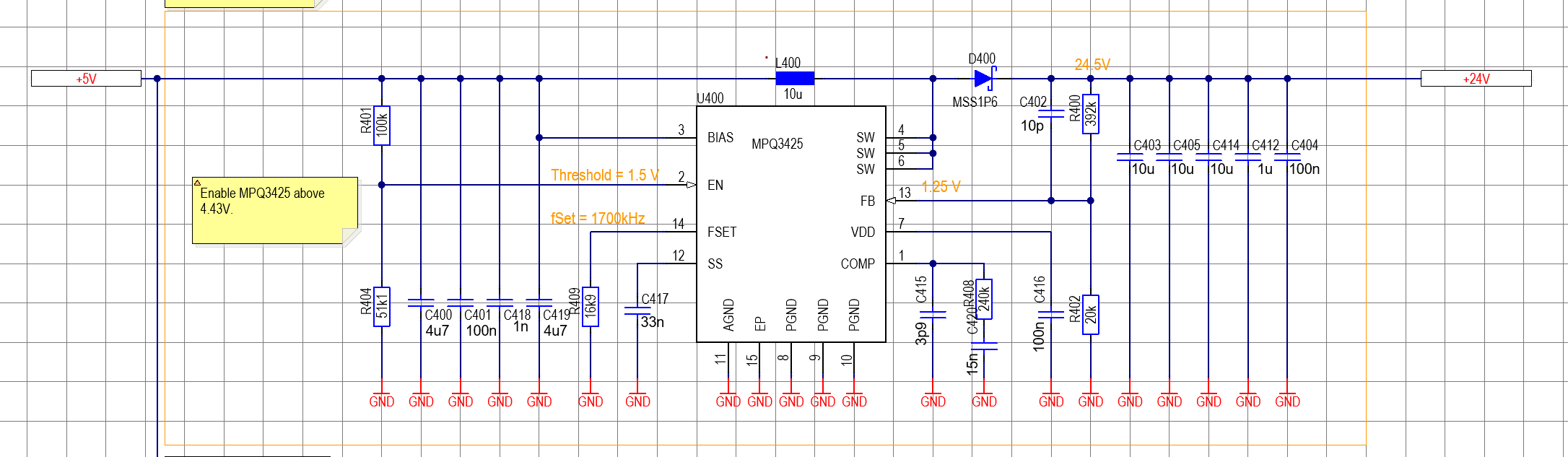
We are trying to get the MPQ3425 to work for two voltages:
5VDC to 24VDC
5VDC to 36VDC
In both cases, the output does not reach the target value (somewhat 19V for the 36V regulator) and as soon as load is applied, the voltage drops.
Any hint is highly appreciated.
Do you have an EVAL board? What is the FB pin voltage? What is the Comp pin voltage. These two questions are to understand if the control loop is satisfied or not. Is the paddle soldered down or not sometimes not and this will cause erratic operation.
Hello,
No, we do not have the Evaluation Board.
The FB Pin Voltage was lower than it was supposed to be. We measured 1V on the FB Pin.
I assume COMP voltage should be 0V ideally? We did not measure the comp voltage yet.
So reading between the lines, there is no general issue with the schematic but you question if the center pad is soldered correctly?
Thanks
Martin
The questions around voltages at the FB pin and the COMP pin speak to “what is the IC thinking” . If the FB pin is low the COMP pin should be high ( asking for maximum power) . Things I would worry about, is the layout good? maybe you have high currents routed through a single 10mil via? That netlists and error checks fine but usually isn’t. What is the saturation rating of you inductor? Ideally it is over the peak current of the IC. Is the layout good? EVAL boards are helpful for comparison. Finally the exposed paddle parts can sometimes be troublsome so maybe the pad didn’t get soldered and this can certainly lead to weird operation.
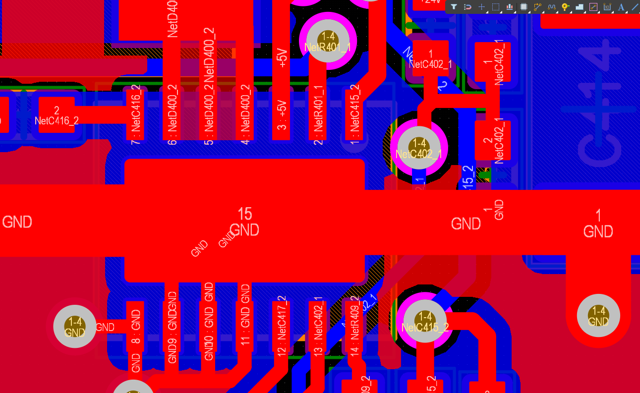
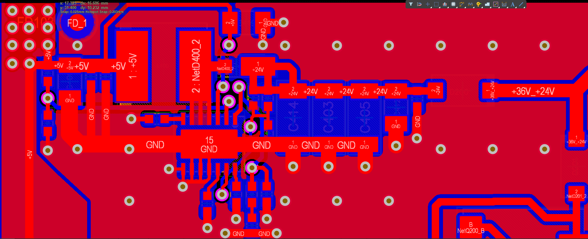
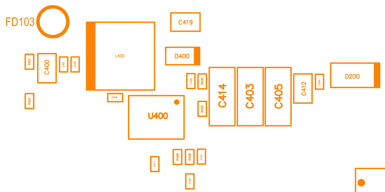
Here are two pictures showing the routing. If you can point out obvious design flaws, that would be helpful.
The inductor is LQH5BPN100MT0L which is rated for 1.6A Saturation current. We are consuming about 100mA
@24V. Do you think that may be the issue because the Chip can do more?
The paddle to be soldered fine, we have tried on several boards, all with the same results. We would have anticipated the paddle at least once soldered ok and the Chip to be working.
Upload Schematic, Layout and Assembly Drawing from 24V Boost Converter
Hello,
Here is the measurements you were looking for:
| Constant Current (mA) |
Vout |
COMP |
FB |
| 0 |
25.3 |
1.16 |
1.26 |
| 10 |
15.7 |
2.03 |
0.85 |
| 20 |
13.8 |
2.03 |
0.703 |
| 30 |
11.8 |
2.03 |
0.626 |
| 40 |
10.84 |
2.03 |
0.57 |
| 50 |
10.3 |
2.03 |
0.565 |
| 60 |
9.7 |
2.03 |
0.519 |
| 70 |
9.3 |
2.03 |
0.52 |
| 80 |
9.1 |
2.04 |
0.516 |
| 90 |
8.9 |
2.05 |
0.515 |
| 100 |
8.8 |
2.05 |
0.508 |
We also checked on the paddle, that appears to be fine. We increased the inductor saturation current to 3.5A, that did not help.
So still, we have no way of getting the booster going.
Any advice is highly appreciated.
thanks Martin
Hello jshannon,
Problem still exists, tried a lot alread and it still refuses to regulate output.
Please advice on the issue at hand so that i can be resolved.
Thanks
Martin
Hello jshannon,
I am closing the ticket now. We will swap the booster to a product of another supplier since we have not been able to make it work and evaluation kits are not available currently. I appreciate you promising to answer within 24 hours, but an initial response is pretty much useless without follow ups.
Martin
Hi martin, I was wondering which supply did you end up using ?