Hello,
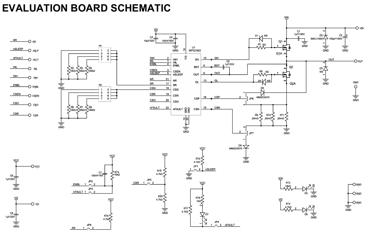
I am designing a driver stage on a low voltage inverter 80Vdc max with the MPQ1922. I want to measure phase current through the low side fet using the current sense amplifier available on the product. For this I have a few doubts:
- As the CSP will be connected to the switching node of the inverter, this pin will have to be protected. In the datasheet you show 2 diodes as protection mechanism but there you depend on the sign of the Vds when the fet is on to polarise the diodes. Plus the smallest Vf for 100V blocking diodes is still big. Do you have any other recommendation? Like an external mosfet connected to the same gate opening the measuring path when LS is on and closing when not
- How does the MPQ1922 handles the CSO pin when the LS fet is ON and when it is OFF? When it is OFF does it pull down the output voltage (as the voltage is of no use) or does it continuously amplify the CSP and CSN regardless if the LS is ON or not
Thanks and regards
Diego