Hi,
The datasheet specify that the two SW pins should be connected together, but the example in the datasheet showning a parallel operation show these as not connected???
The SGND1 pin is used for the buck 1 and 2 voltage feedback and SGND2 pin is used for buck 3 and 4 feedback, sense ground.
In the demoboard for MPM54304 the schematic show the connection but only on one of the outputs.
What about Vout2 and Vout4?
Hi Thomas,
Great question. The datasheet simply does not show the SW pin connection, but for parallel mode, follow the ‘Pin Functions’ guide. Tying the SW nodes together for parallel mode needs to be done between the SW1 and SW2 pins.
Could you clarify what you mean about Vout2 and Vout4? Perhaps you can also explain what you are trying to do and we can help with this process.
Best,
Tyler
Hi,
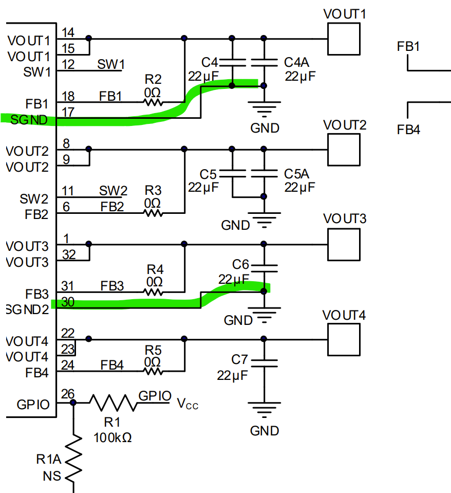
Yes as shown in the attached picture, the green connection show how SGND1 is connected to VOUT1 and SGND2 is connected to VOUT3. What about VOUT2 and VOUT4?
Hi,
SGND1 applies to outputs Vout1 and Vout2, while SGND2 applies to Vout3 and Vout4. Vout2 and Vout4 are also grounded by these connections. Just make sure you have your decoupling capacitors between the outputs and GND plane as well.


Best,
Tyler